Outside of my normal assigned graded class projects, I also took on an additional project in the Canadore Structures shop. Rebuilding the forward portion of a scrapped Cessna 150. My understanding is that the school acquired two airframes that had been scrapped to be used as rolling engine mounts for the AMT students. The trouble was that there wasn’t enough left of the airframes to attach an engine to. This is where I came in.
I was not the first student to tackle this project; in 2020 (prior to covid restrictions limiting after hours access) structures students had attempted this job, but made a few mistakes along the way. Before starting my work, I had to undo most of their work. This involved scrapping the installed skin section which had not been fitted correctly, and restarting, from scratch, the work previously done on building a new firewall as none of the accessories had been made and all the rivet holes were in the wrong places.
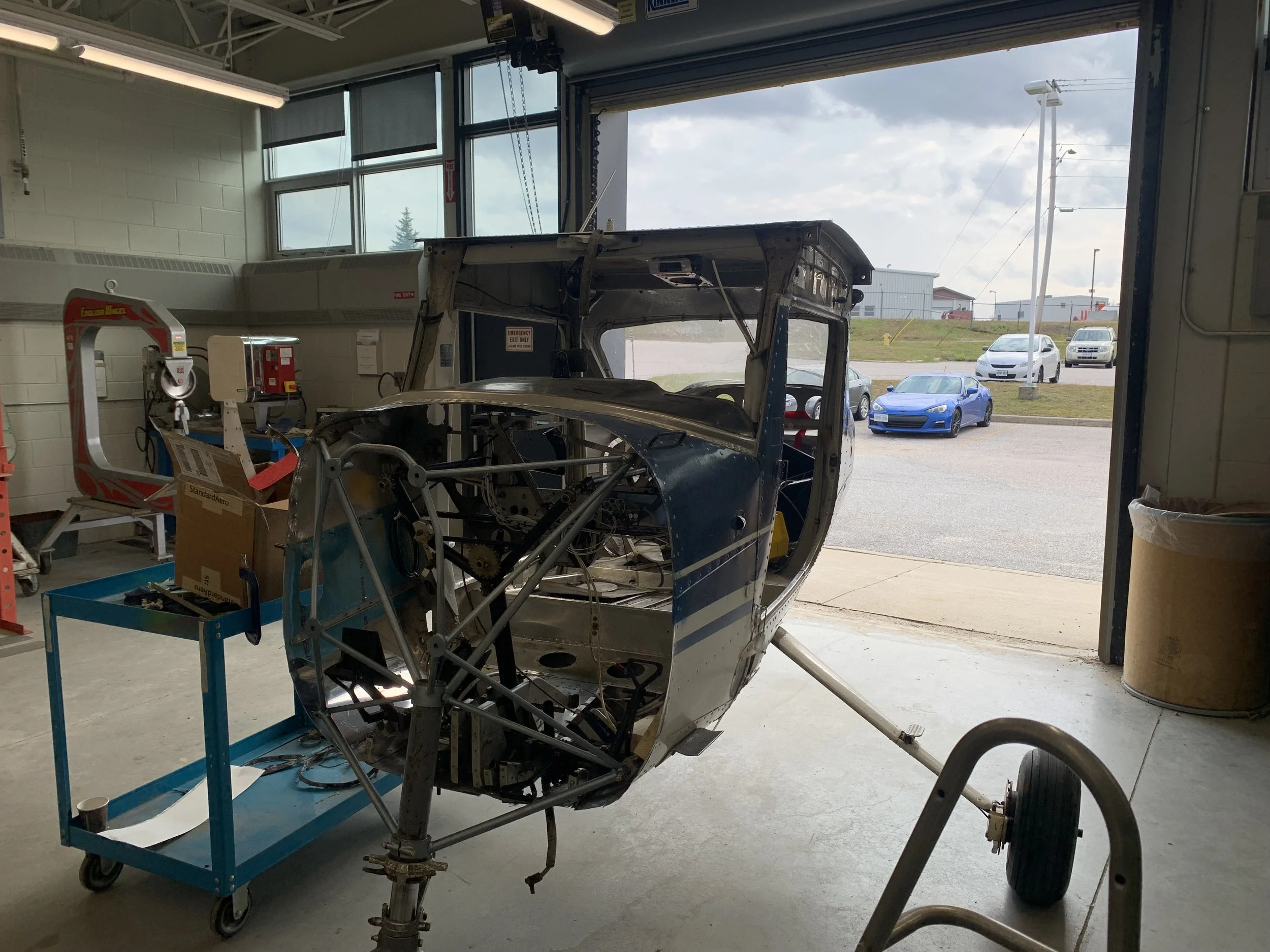
The 150 rolled into the shop. This is where I started.
In the shop
That skin looked nice but because it was not fitted with all the internal structure in place, it didn't fit properly. I had to scrap it and start from scratch.
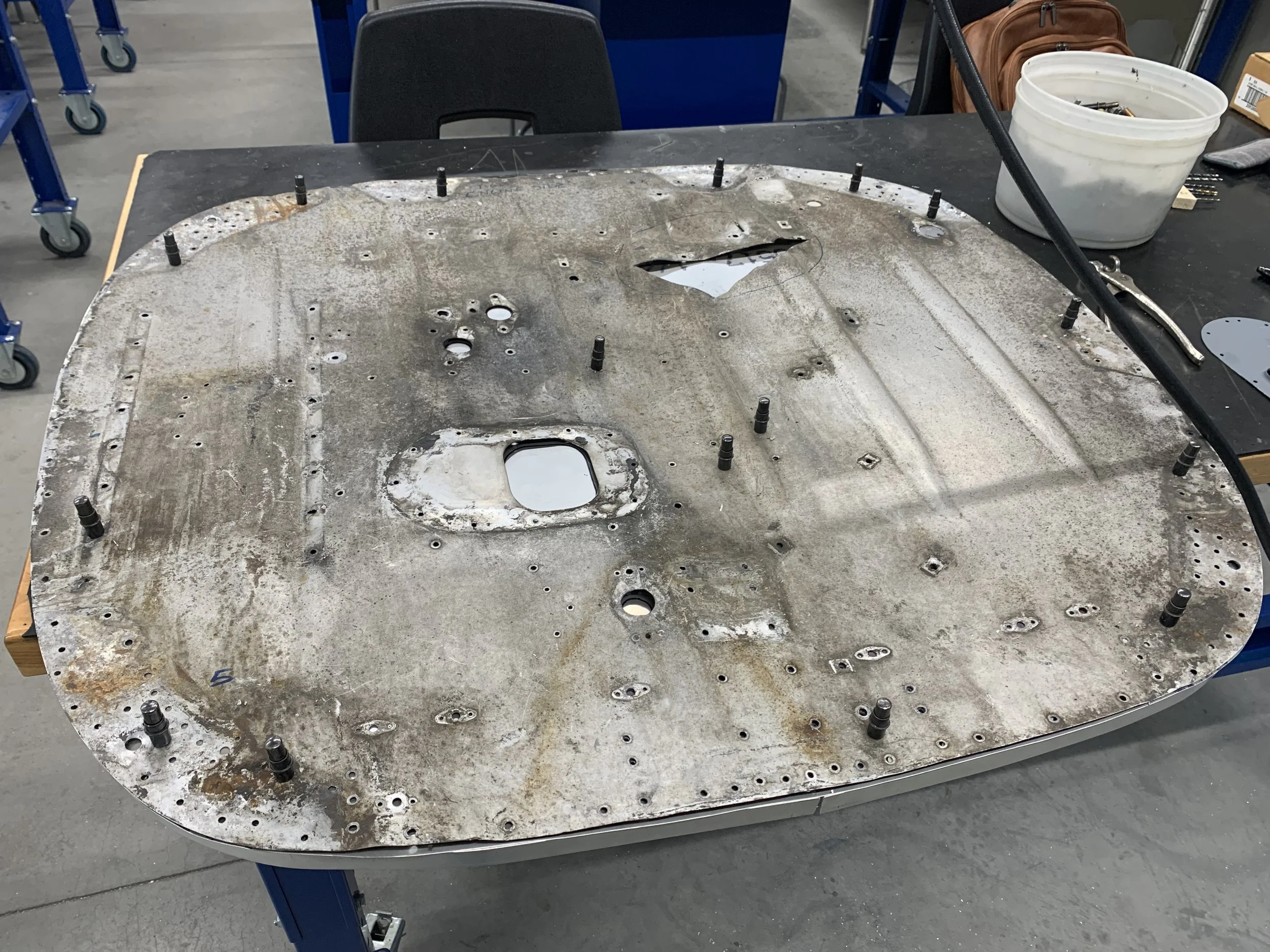
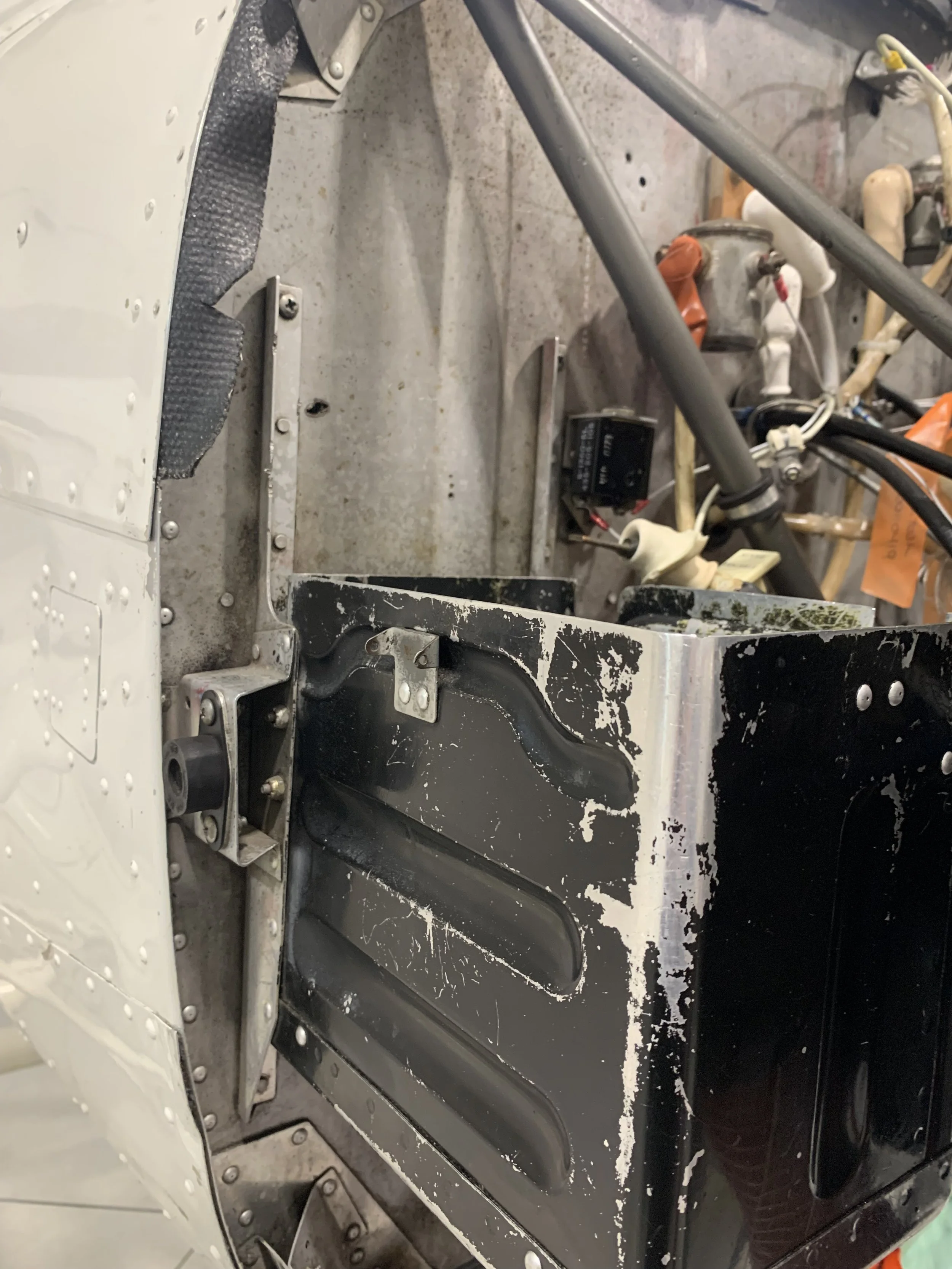
What was left of the firewall. This would be used as a template to create a new one.
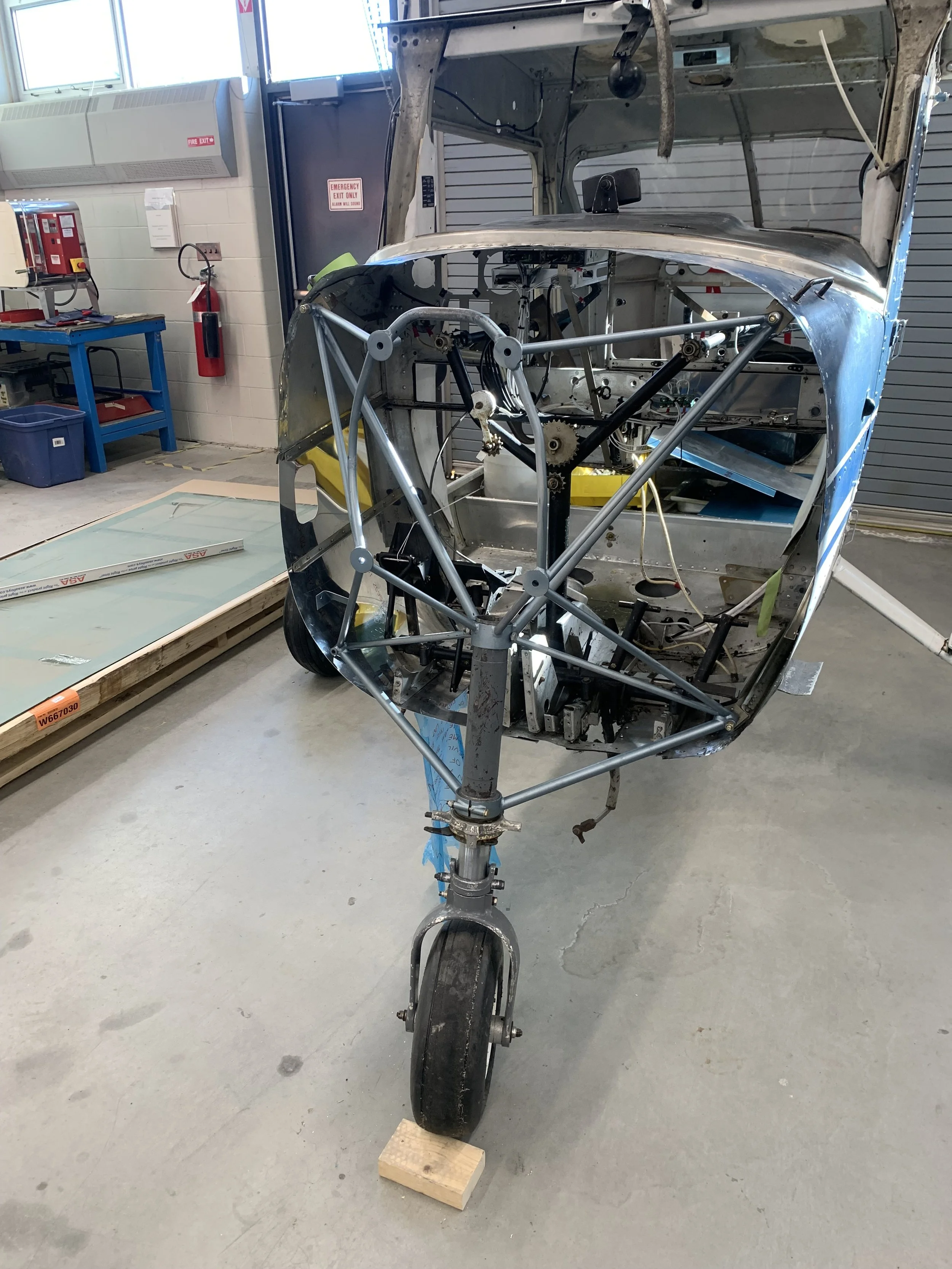
Once the old work had been stripped out, I evaluated what I had left. A rather ratty looking firewall with a giant hole in it, a bent and twisted longeron that was also the lower starboard engine mount, a few scrap parts that were once cowling mounts, and not much else.
Thankfully, the school had another 150 in the hangar that was in much better shape, so that was used as a reference for the majority of my work going forward. My first step was to reverse engineer the firewall accessories such as the mounts for the battery box, the cabin heater assembly, and the dozen or so cowling mounts.
Drawings and measurements were made from the second C-150 in the hangar.
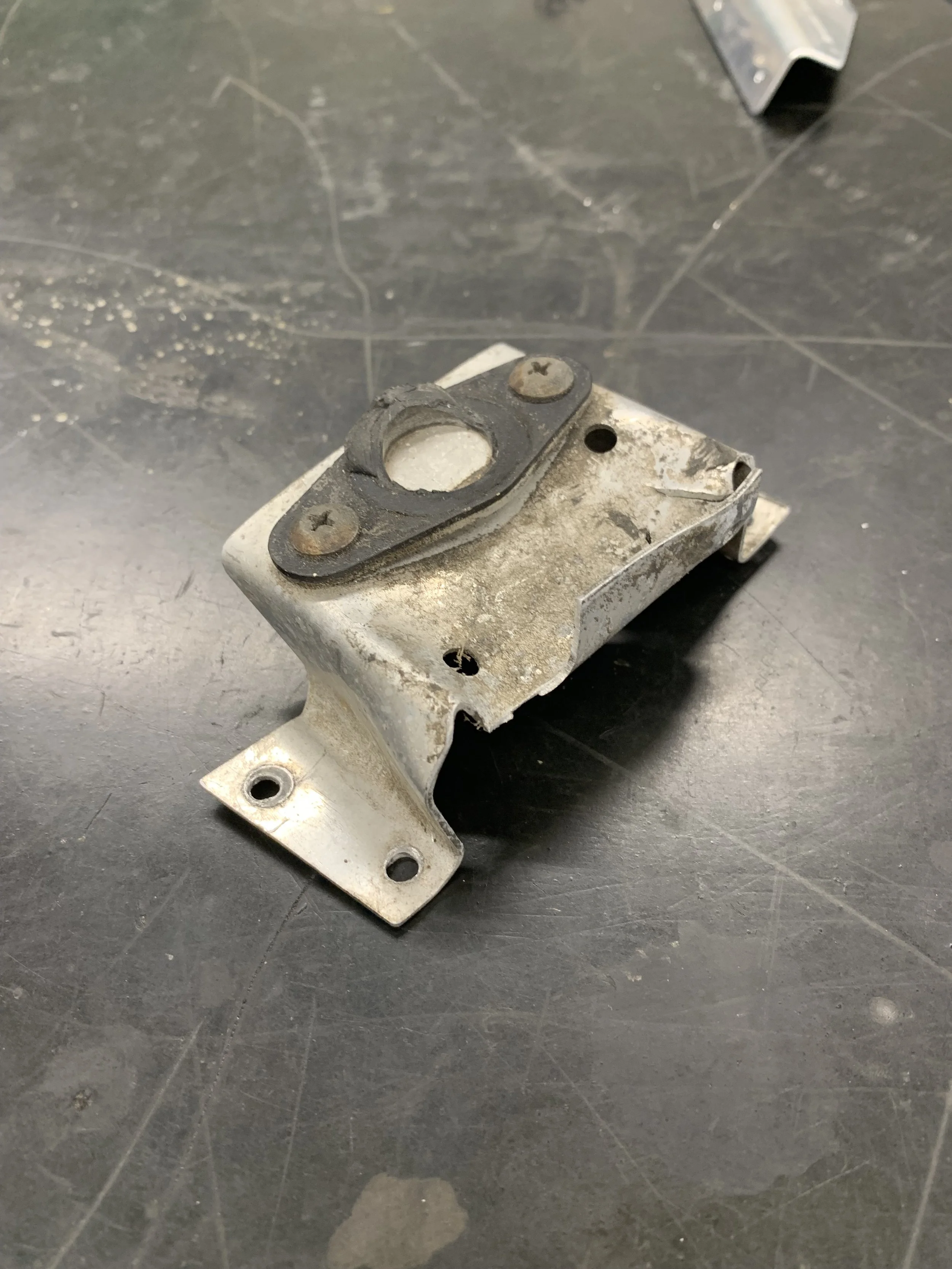
Parts like this cowling mount were also used as templates.
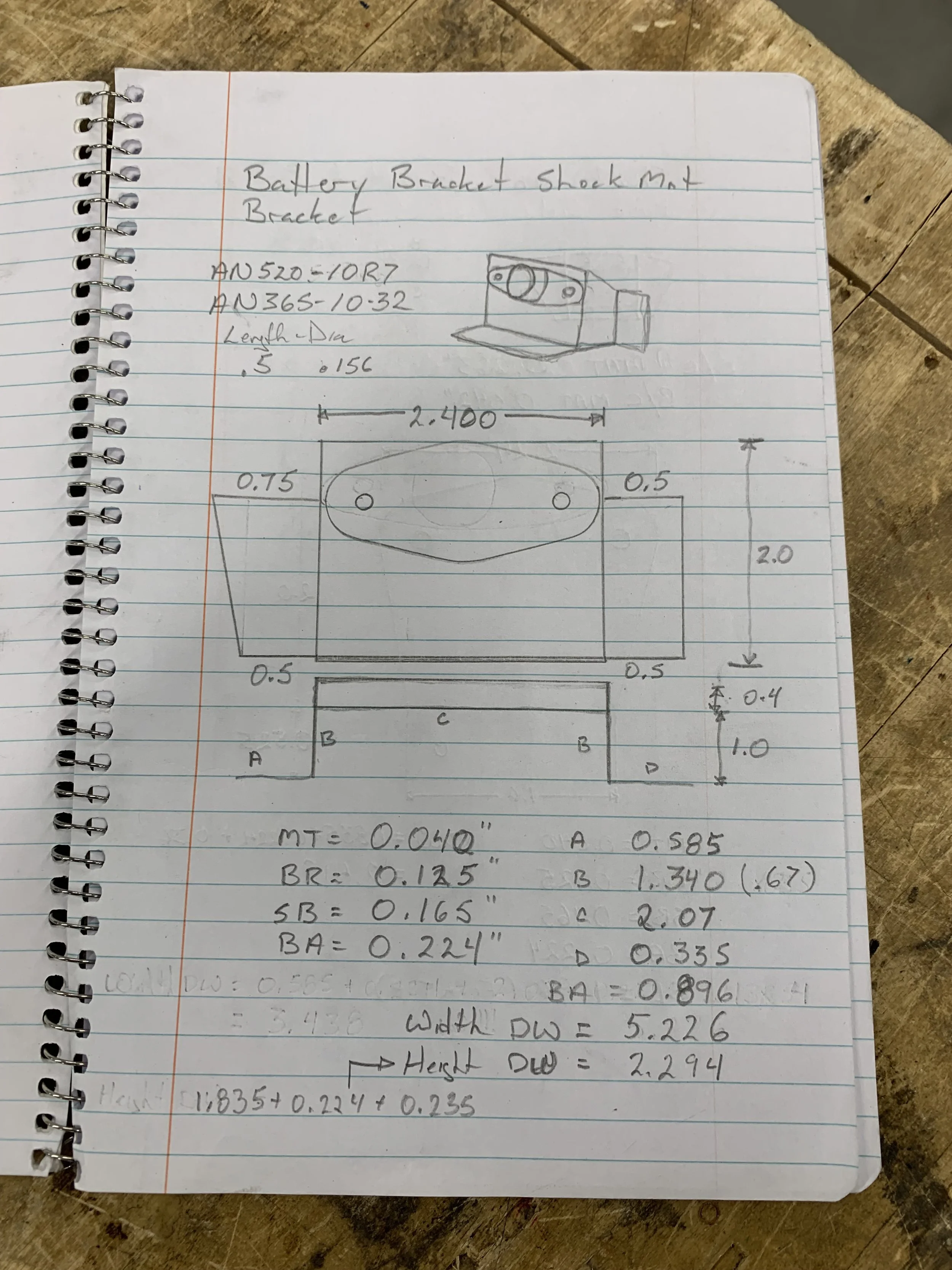
Drawings (even simple ones) were made of all new parts before new ones were fabricated.
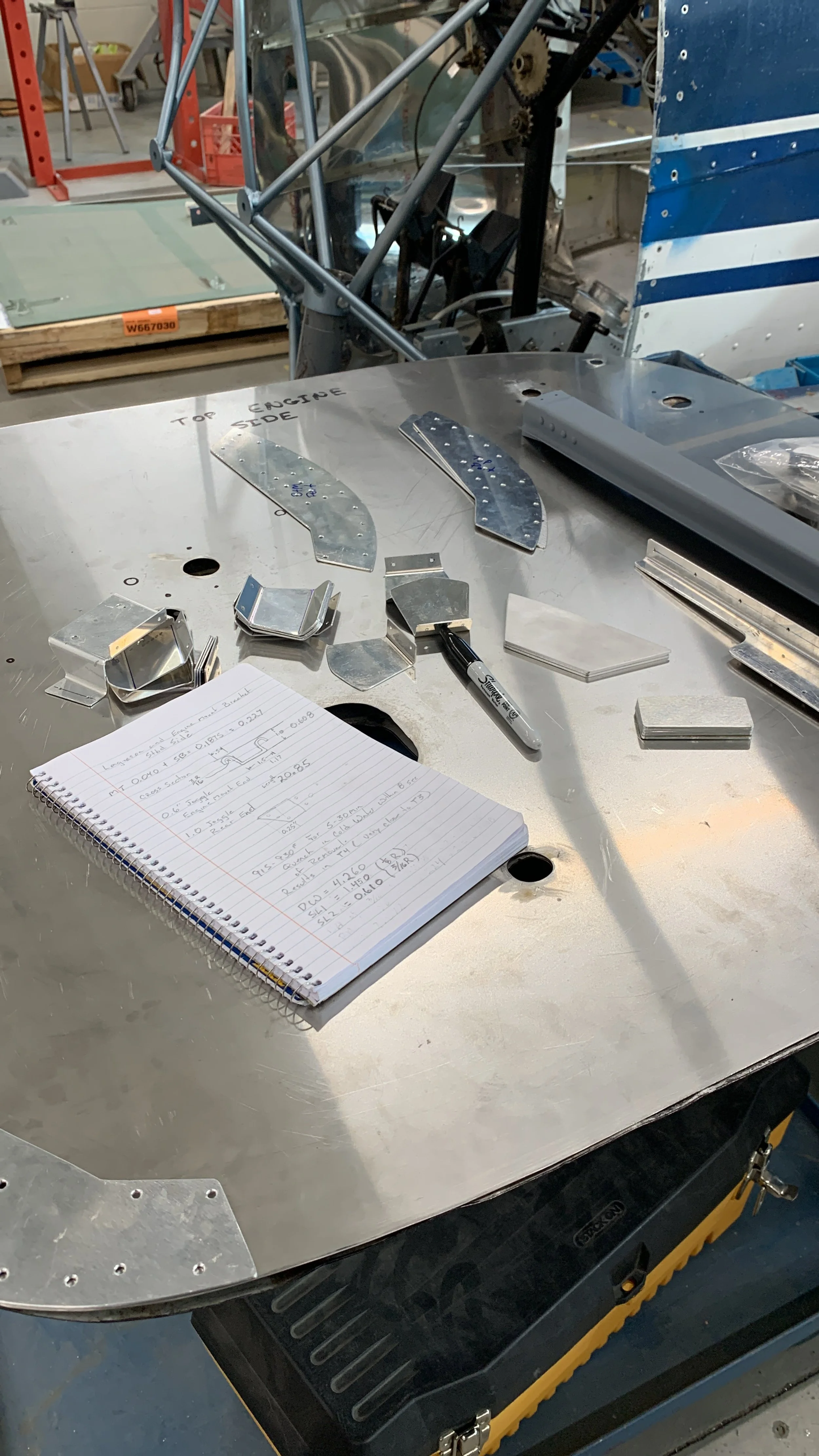
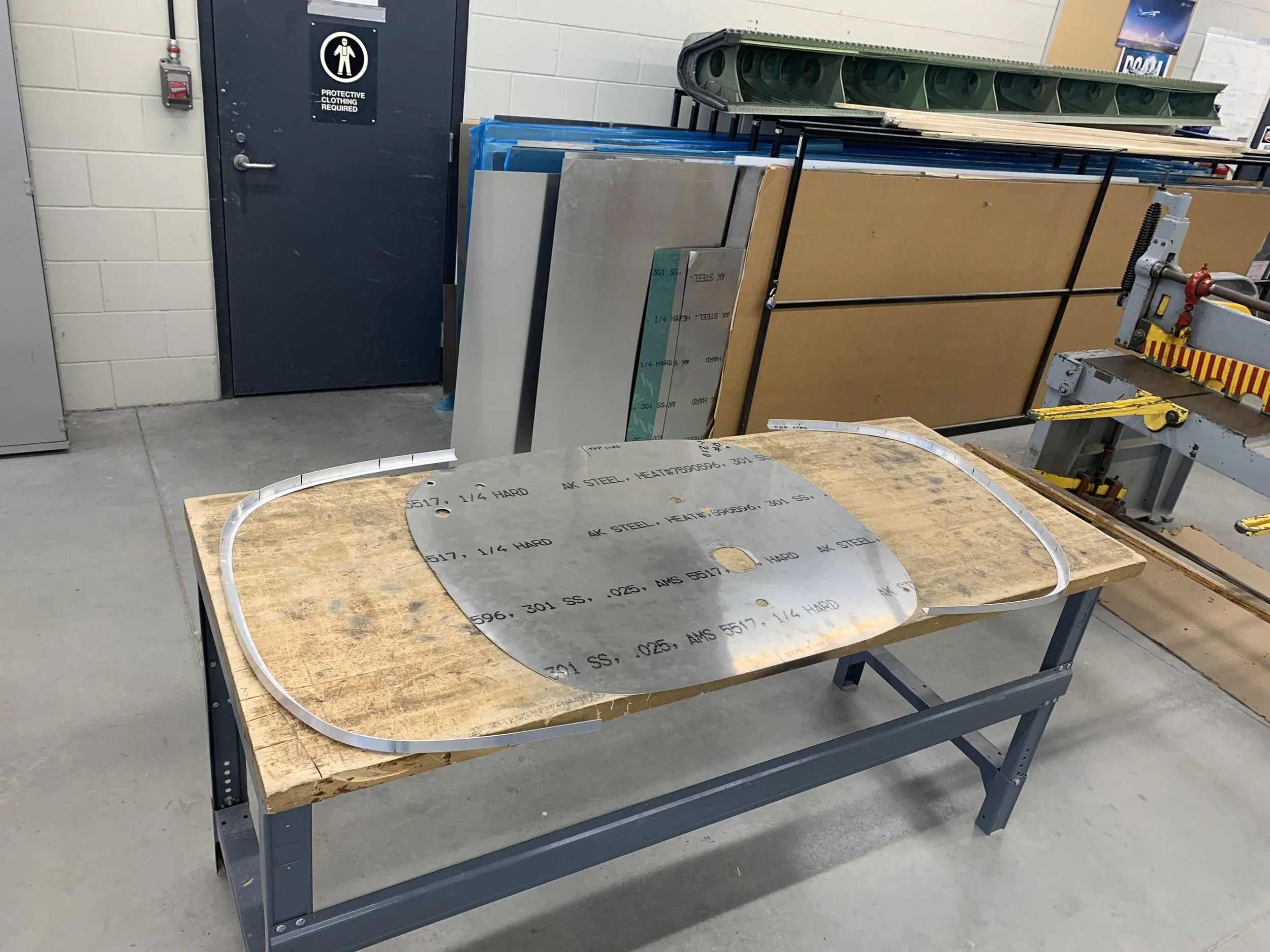
The new firewall cut from stainless steel with several other newly manufactured parts.
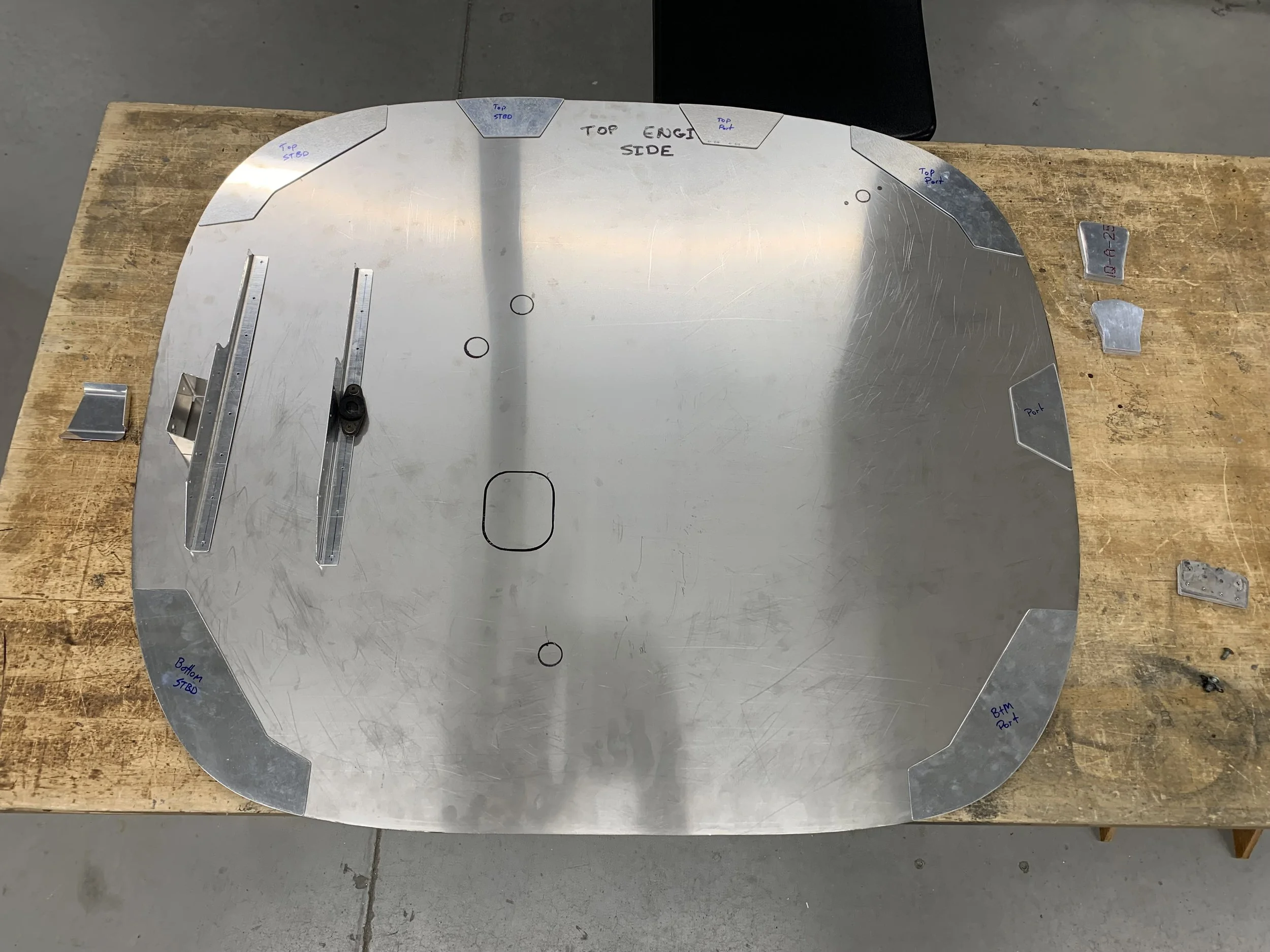
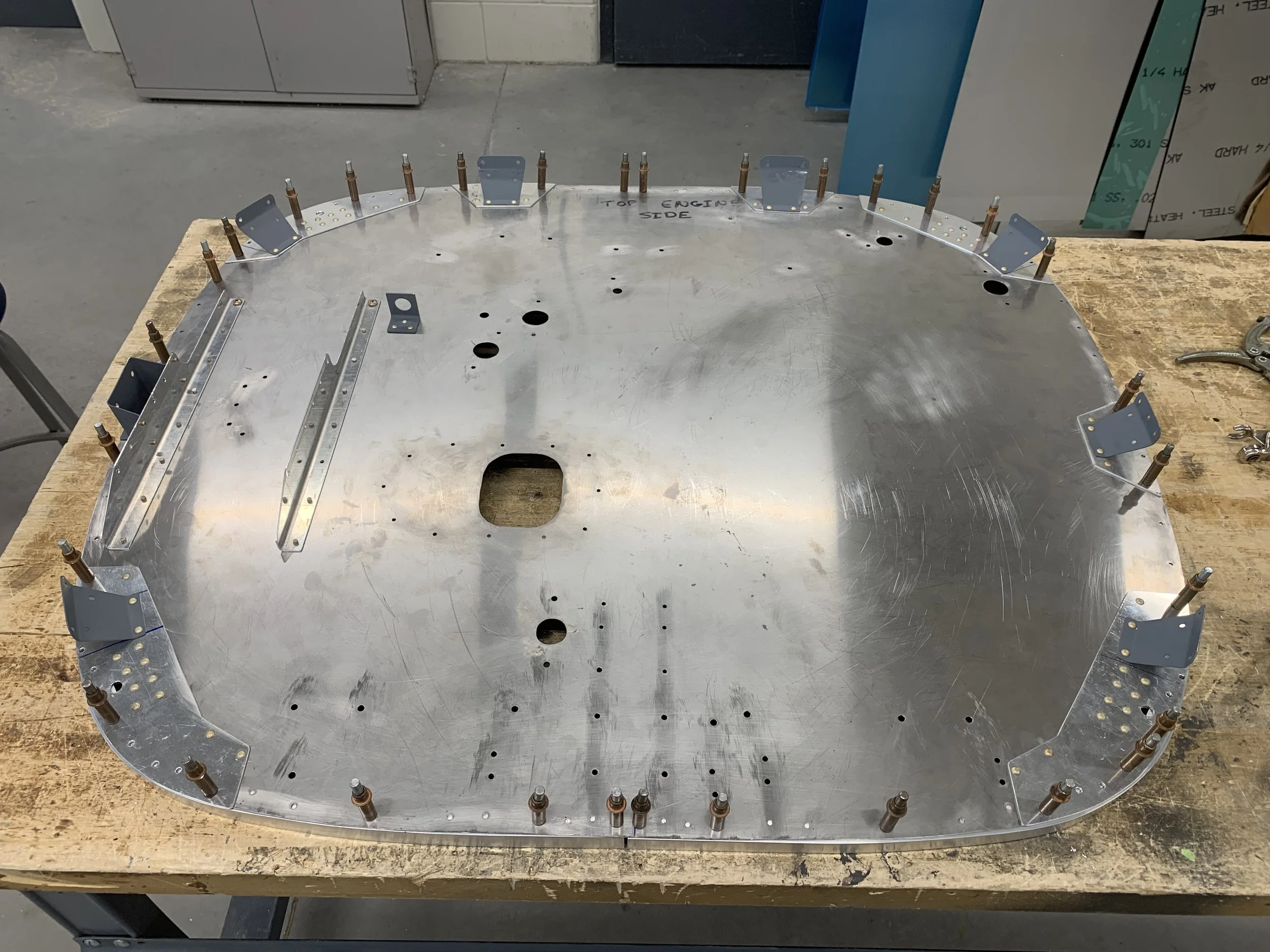
All newly manufactured parts laid out in their places on the new firewall. Doublers and mounting brackets.
Next was arguably the biggest challenge of the project to date, fabricating a brand new longeron and engine mount point. The existing one was well beyond repair so I decided to just make a new one. The only trouble is that involved a lot of techniques I’d never done before. Thankfully, my professors pointed me in the right direction and just let me figure things out from there.
The first step was to reduce the damaged longeron back to drawings, using the good part found on the opposite side of the aircraft as a basis for a lot of dimensions. The decision was made to use 0.040” 2024-O type then heat treat the formed part. The thickness was to match the original part, O type material chosen because it made bending a large radius more practical. Shims were added to a press brake radius bar to increase the radius to that needed, then the flanges of the custom made aluminum hat section were formed around it using forming mallets. After my arms were sufficiently sore from hammering metal, I had a part that, aside from temper and some holes, was an exact duplicate of the original part used. An hour in an oven at 940F, a quick quench, and voila! a brand new longeron. This was then given an acid bath, alodine treatment, a coat of primer, and fitted — a perfect fit!

The original damaged longeron along side the newly made part. The upper radius flanges have just been formed.
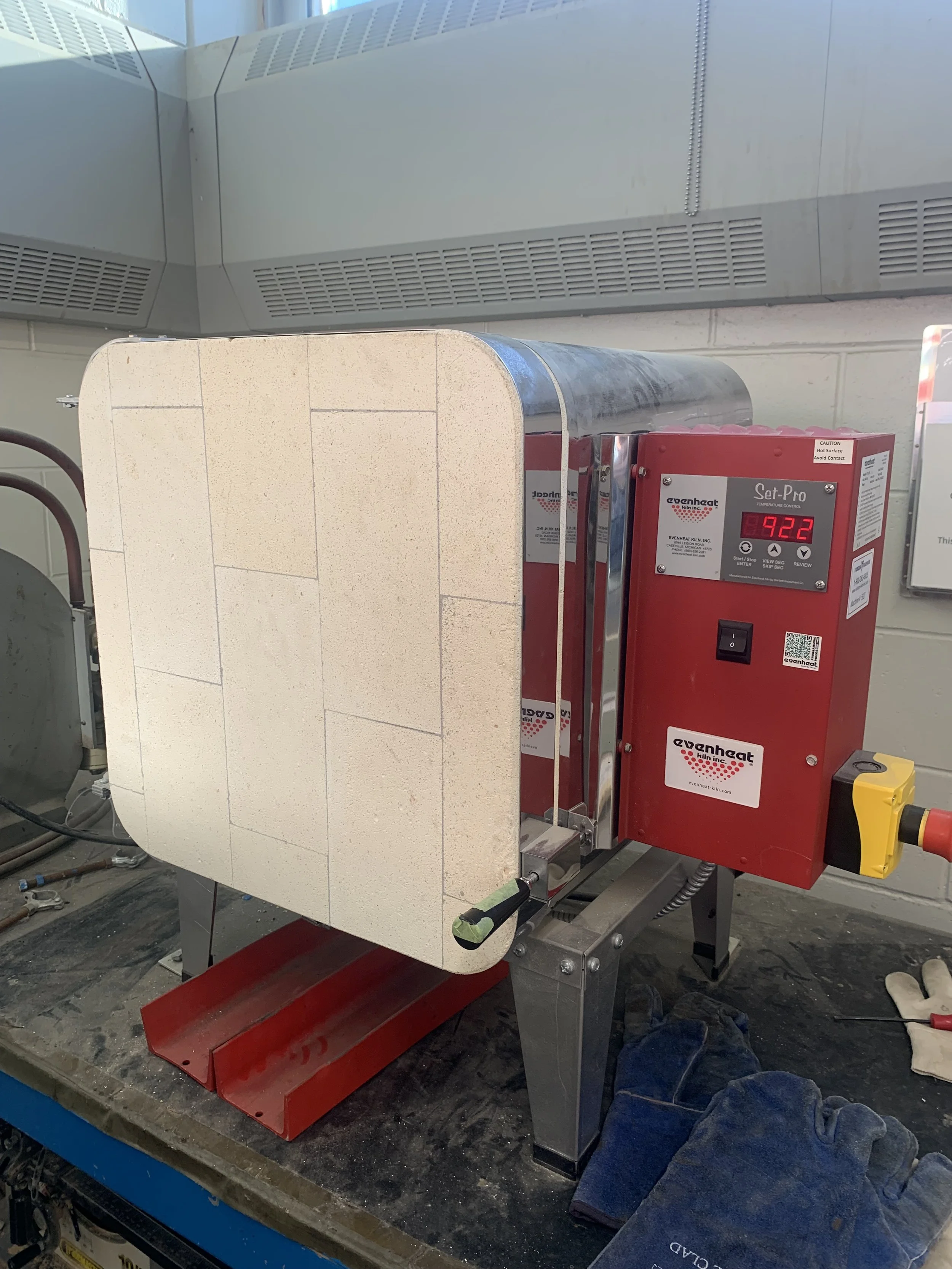
Into the oven for an hour at 940F
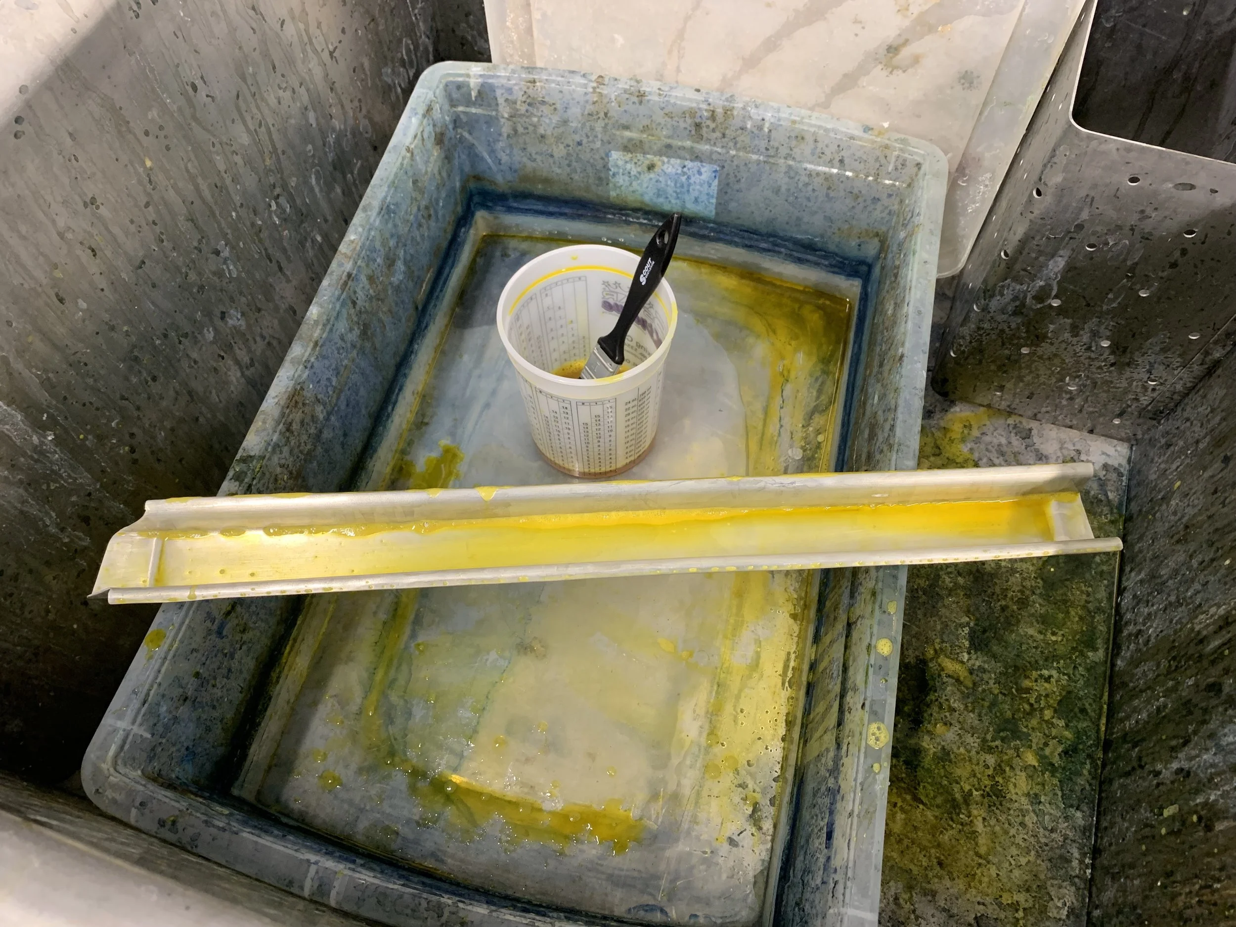
The the part is acid cleaned and treated with Alodine. To save materials, this was brushed on instead of dunked.
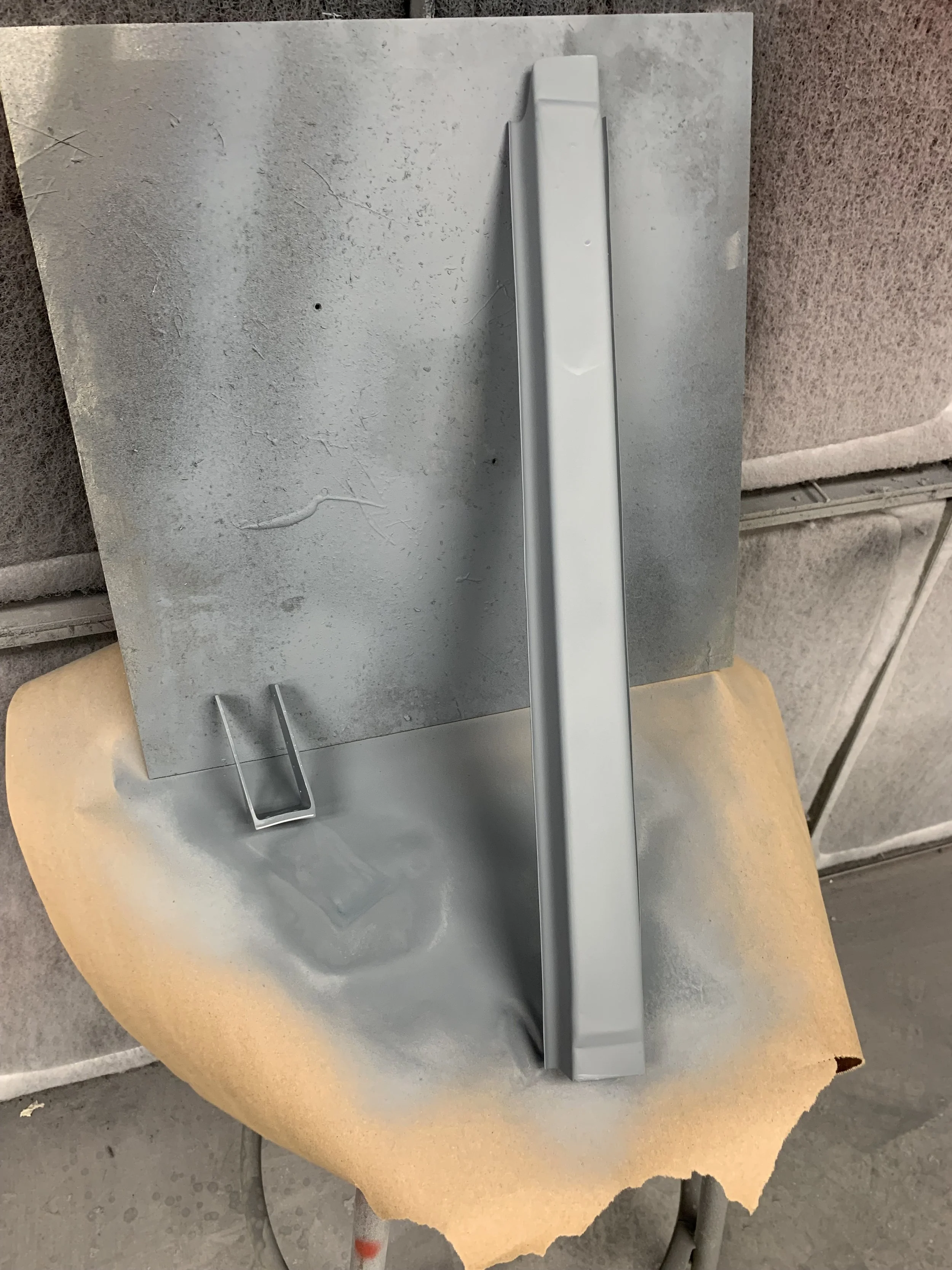
A quick shot of primer. Unfortunately just regular grey auto primer. No green Zinc Chromate here.

The finished part along side the old one.
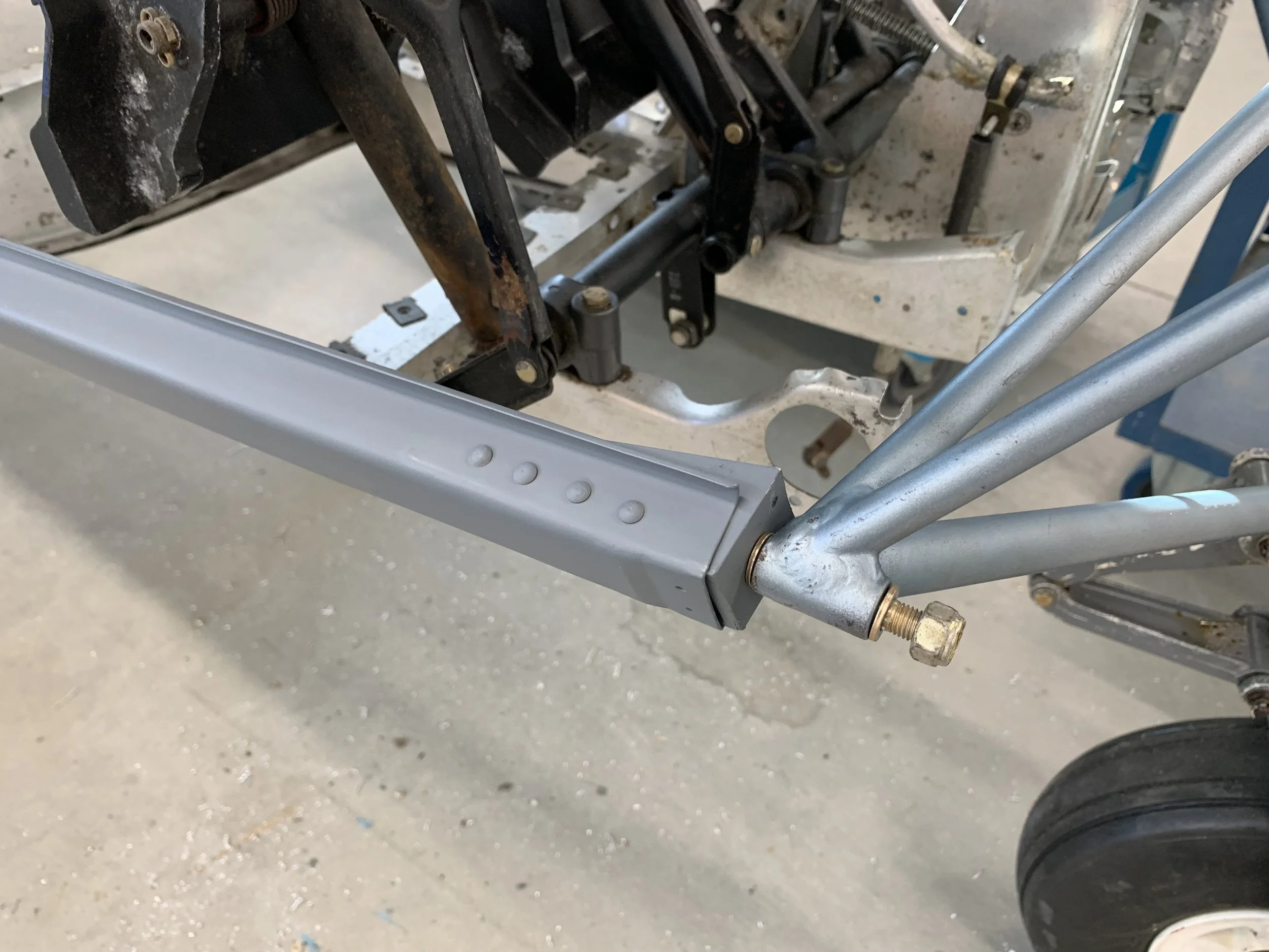
Newly installed on the airframe. Perfect fit.
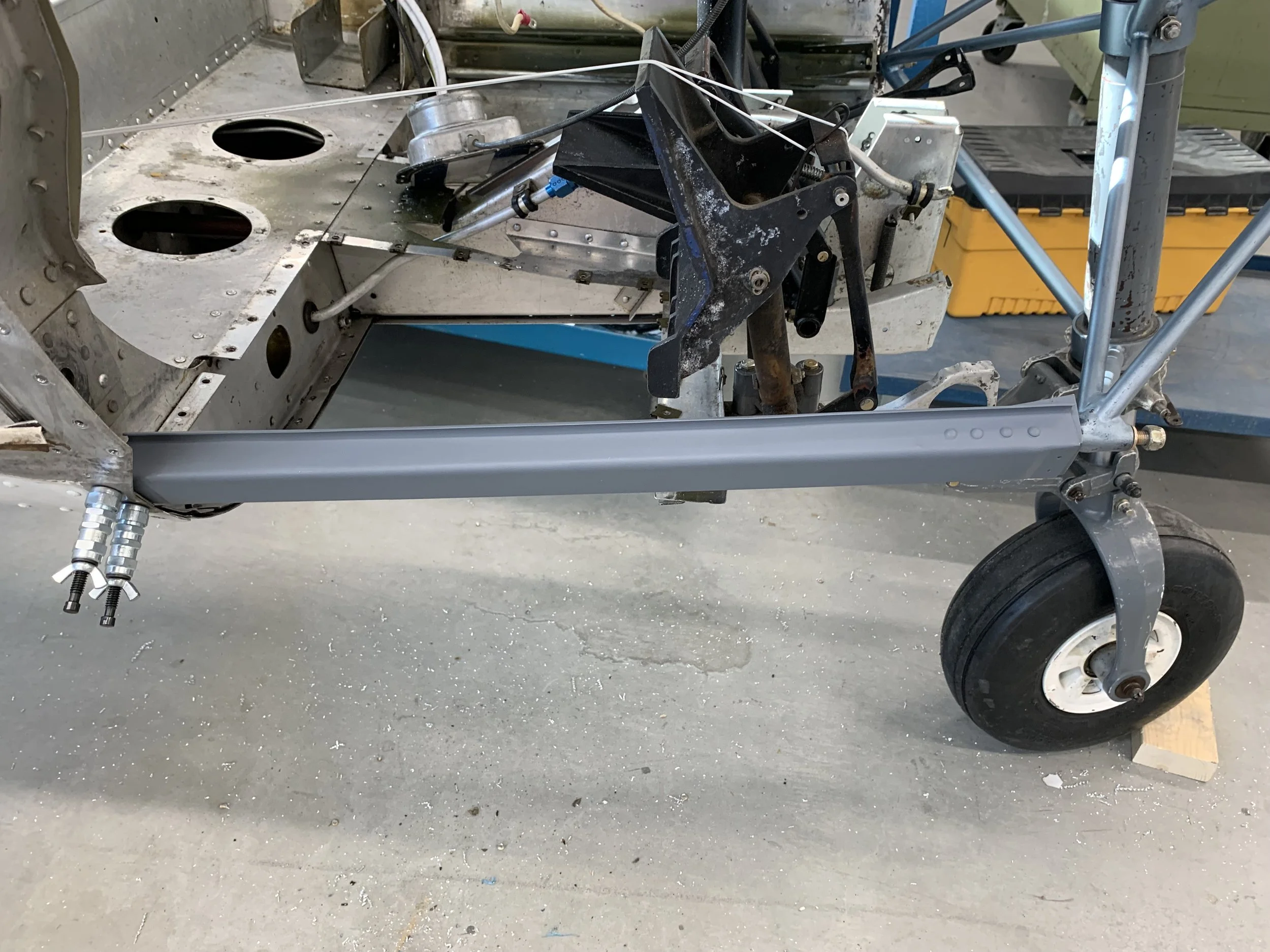
Newly installed on the airframe. Perfect fit.
Now that the engine mount and longeron has been sorted out, it was time to move back to the stainless steel firewall. With all the accessory parts created, it was almost time to mount them, but first, the firewall’s skin mounting edge needed to be created. This was done with some basic aluminum L extrusion, and a shrinker-stretcher, a tool used for bending extrusion into small and large radii. This material was purchased from Canadian Tire, so is obviously not the correct type for use on aircraft, but it’s all the school would provide, so I used what I was given.
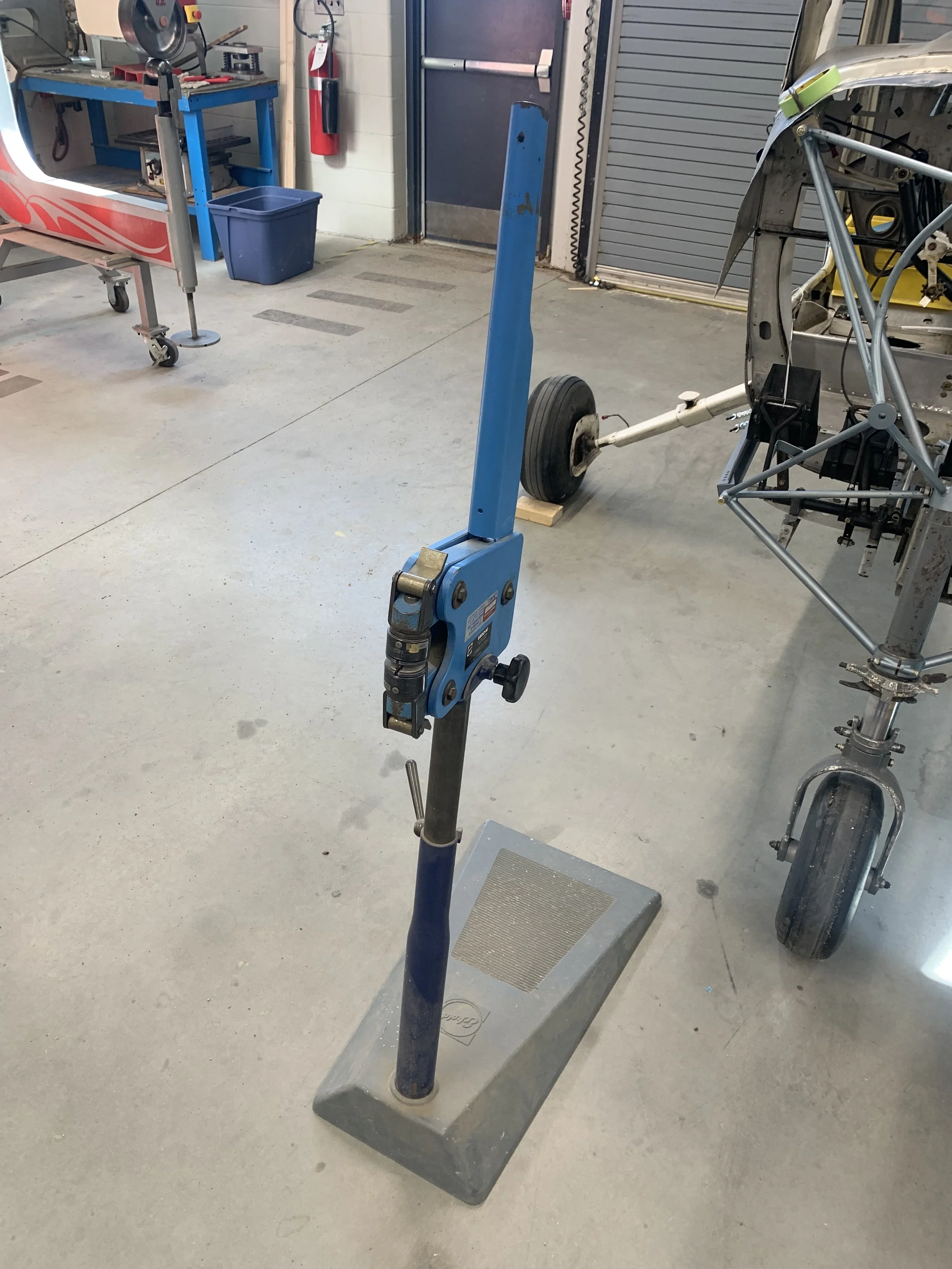
The 'shrinker-stretcher' used to form the L extrusion into the various curves required to fit around the firewall edge.
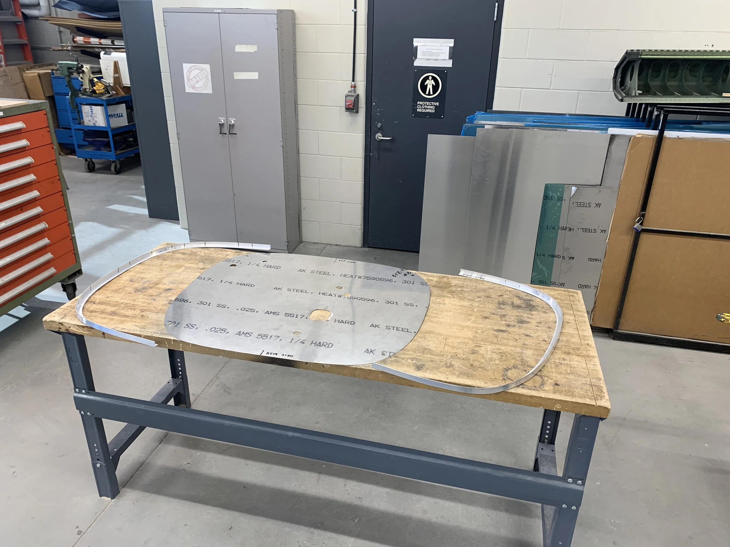
The stainless steel firewall with the left and right extruded edges.
The stainless steel firewall with the left and right extruded edges.

Here the remains of the old firewall are being used as a template for drilling new rivet holes.

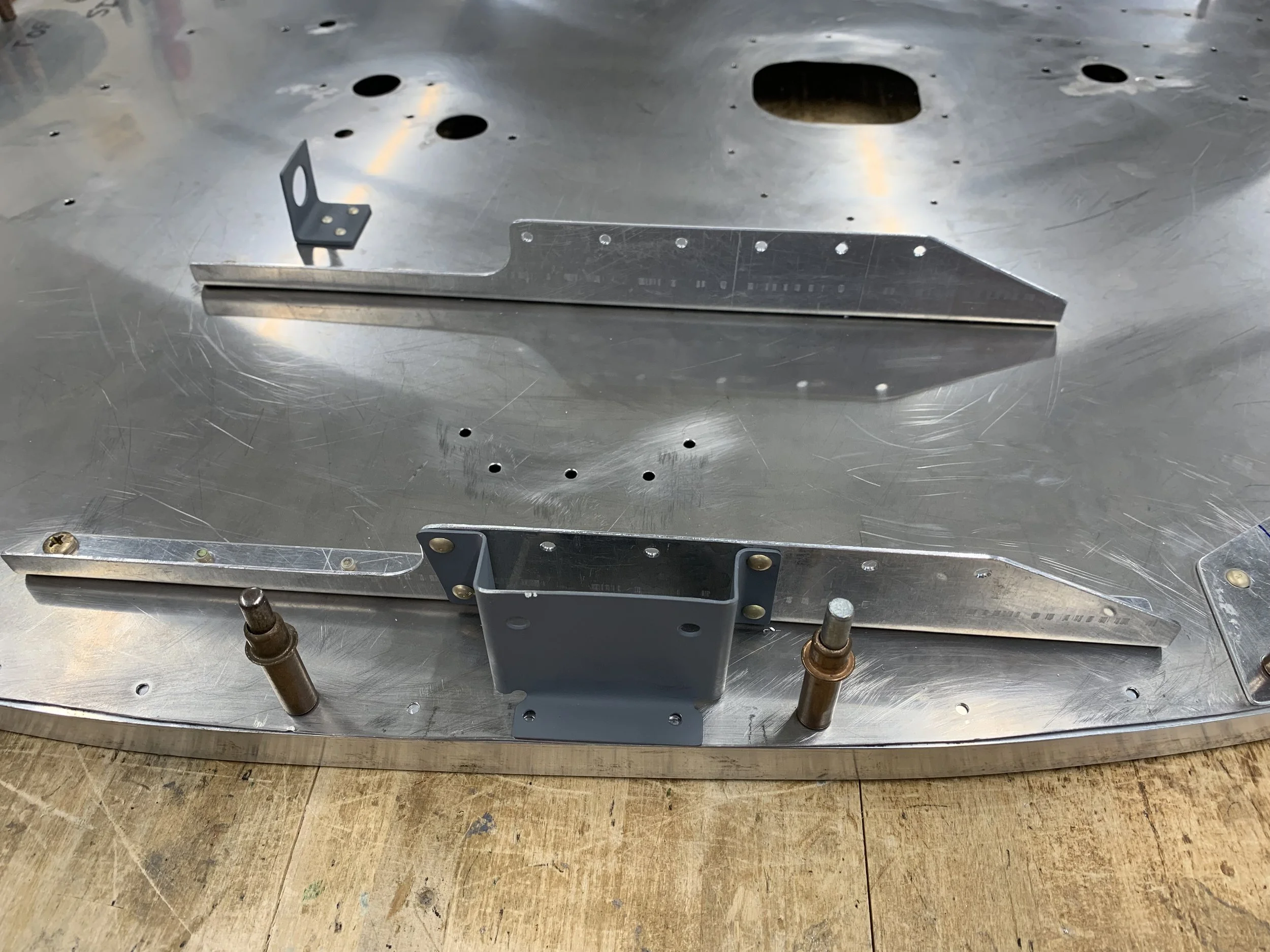
The firewall with all mounting holes drilled and doublers temporarily in place. The IPC page for the duct work is at the top right.

Final assembly of the firewall begins

Final assembly with all doublers and battery box mounts in place.
March the 14th, 2023 was a small milestone for this project as the firewall, with most fittings attached was test fitted to the rest of the airframe for the first time. Everything fit as it should. The next step is to rivet the previously formed extruded edges in place and mount the cabin heater accessories. then the firewall can be permanently mounted in place.
Most of the accessory brackets are fixed in place now and the previously formed L beam extrusion is temporarily fixed in place with clecos.
Accessory brackets fixed in place.
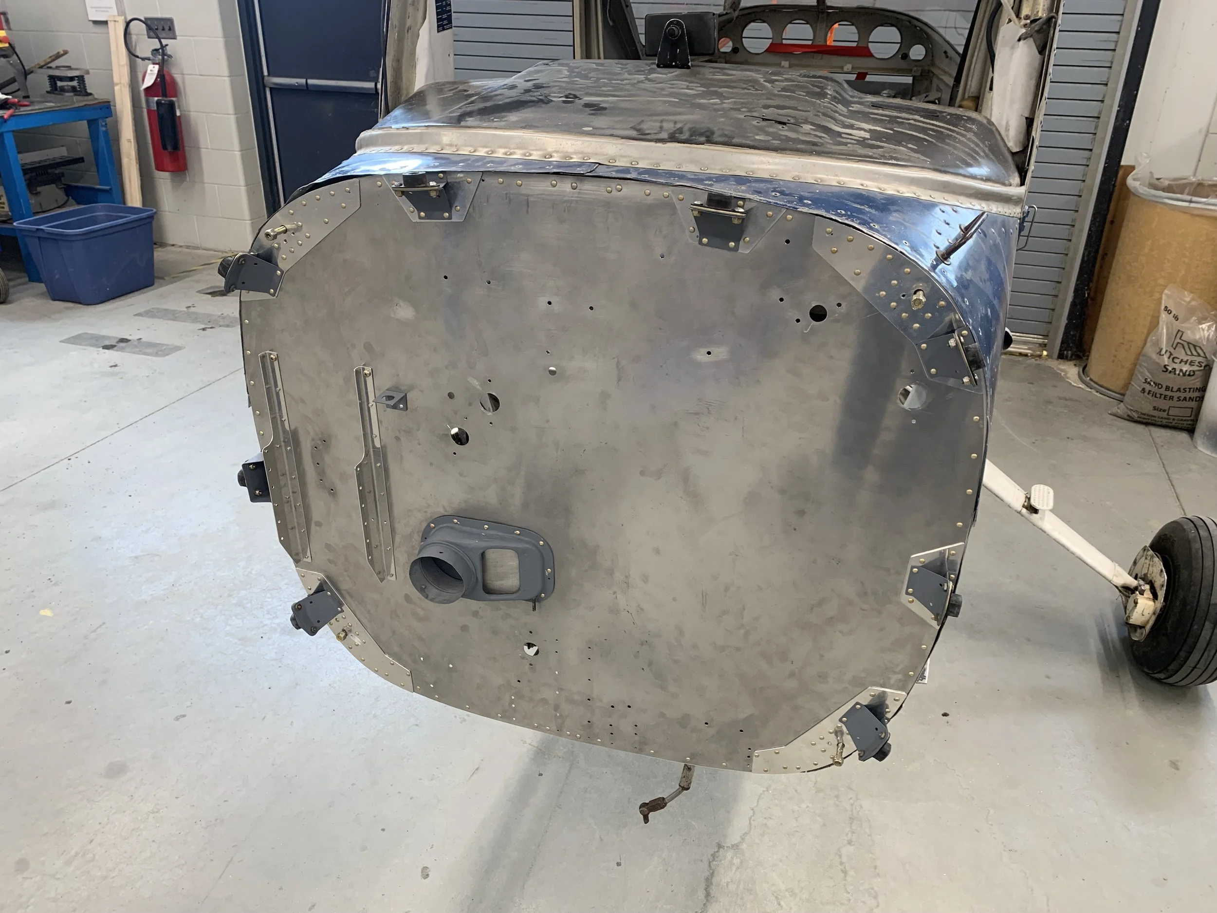
The newly built firewall, with all accessories, finally fitted in place. It has not been riveted yet, this is a 'dry fit'.
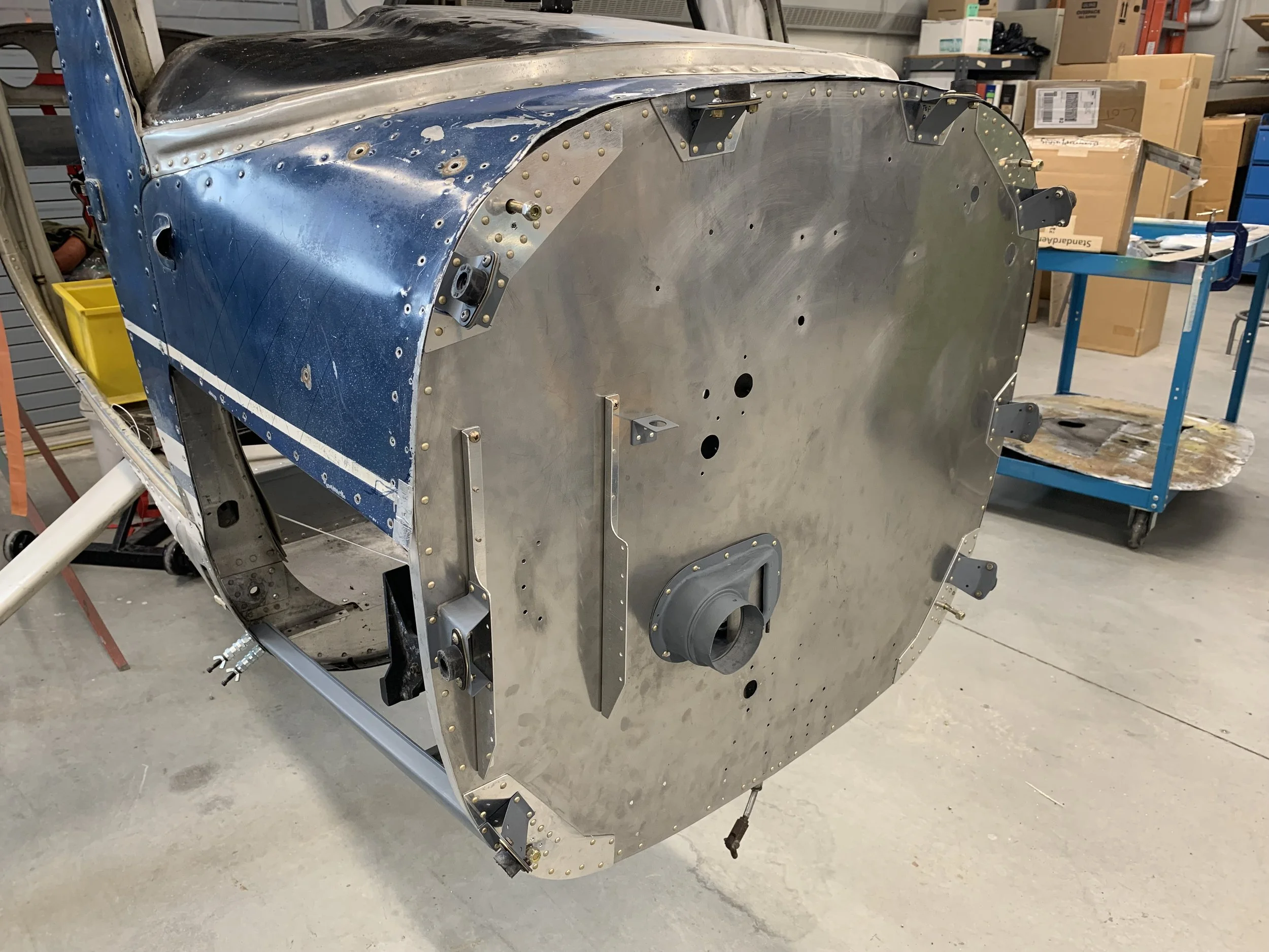
During the dry fitting, the upper right panel (above the missing one) would not conform to the contours of the firewall due to a large damaged area. This area was removed and will be patched.

A large area of the upper right panel removed to repair the underlying structure and to remove the damaged skin.
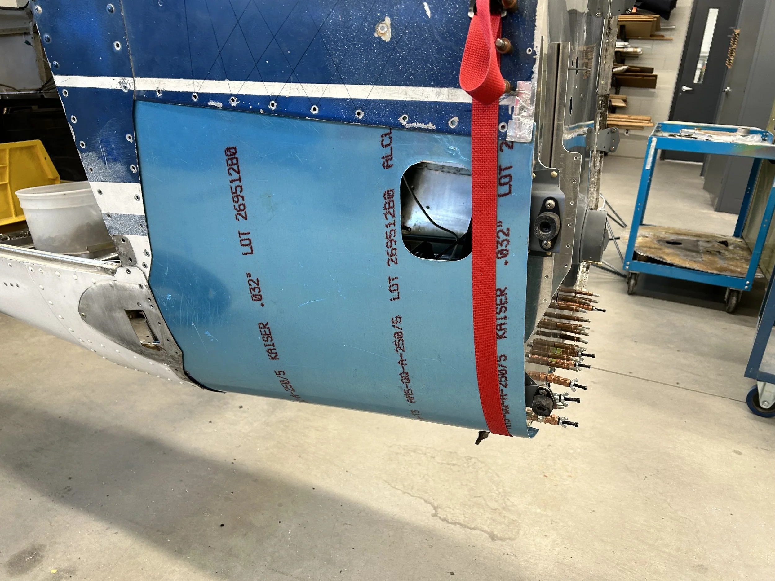
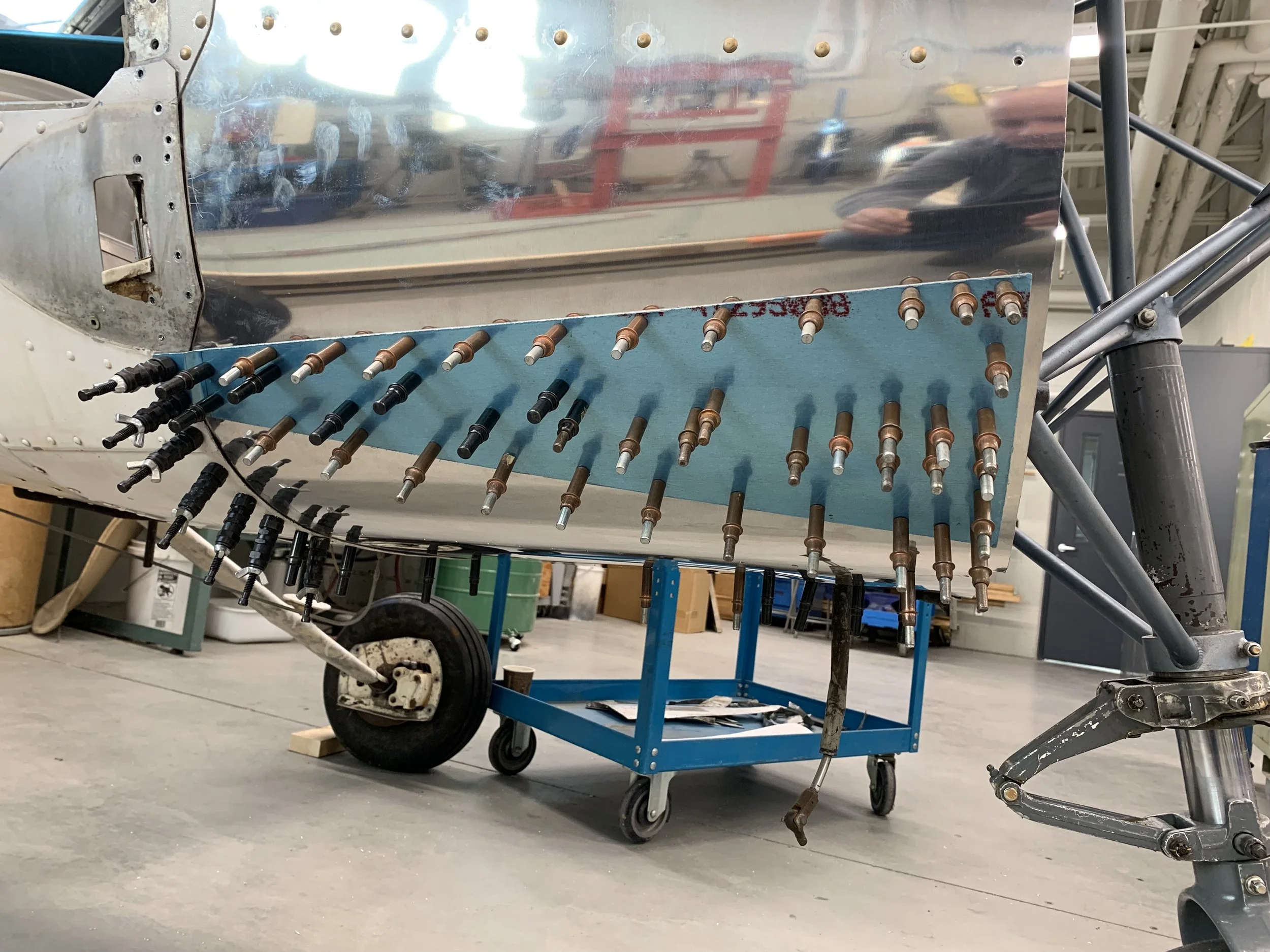
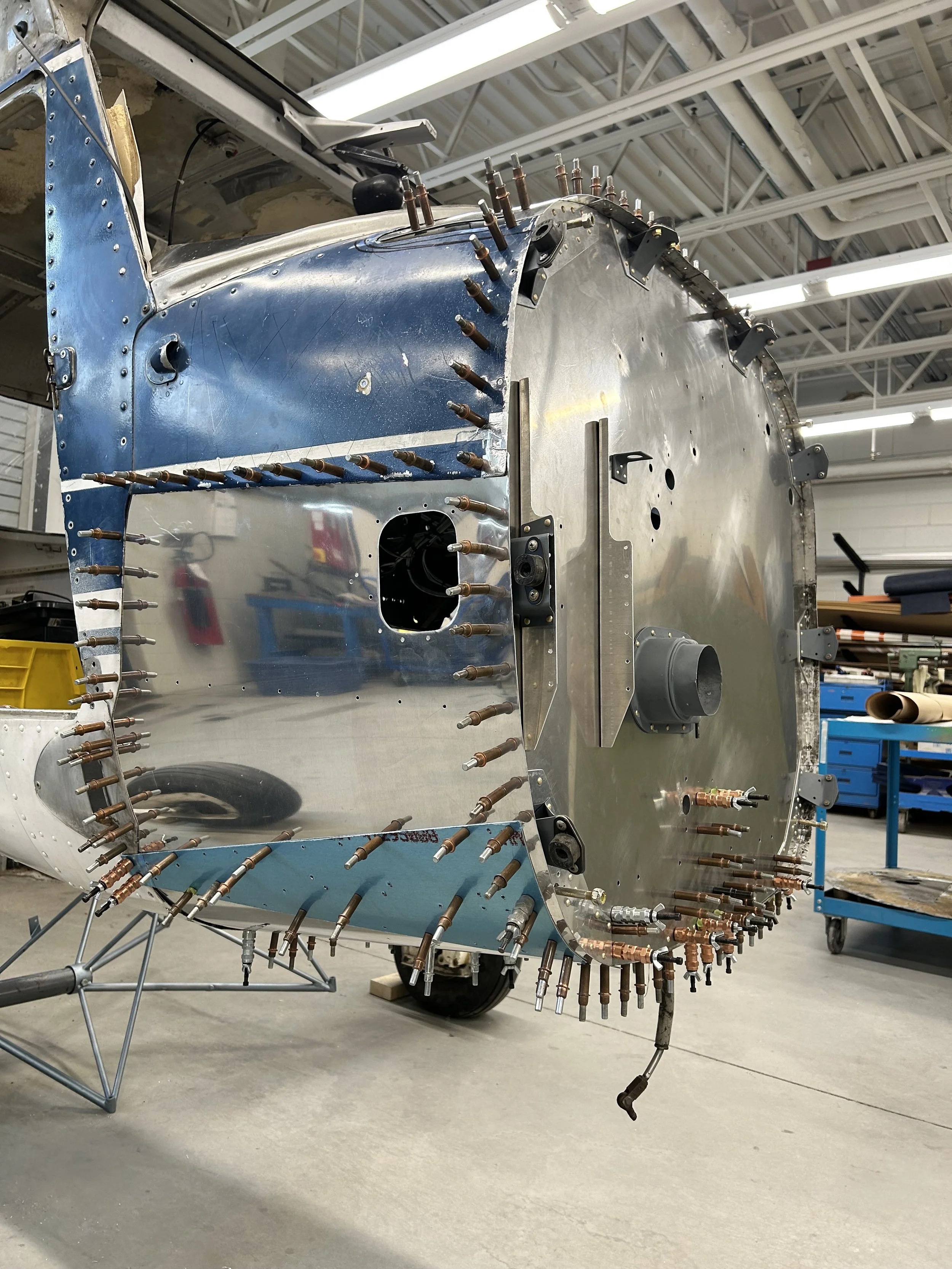
With the firewall temporarily in place, it's time to fit the newly created lower quarter panel.
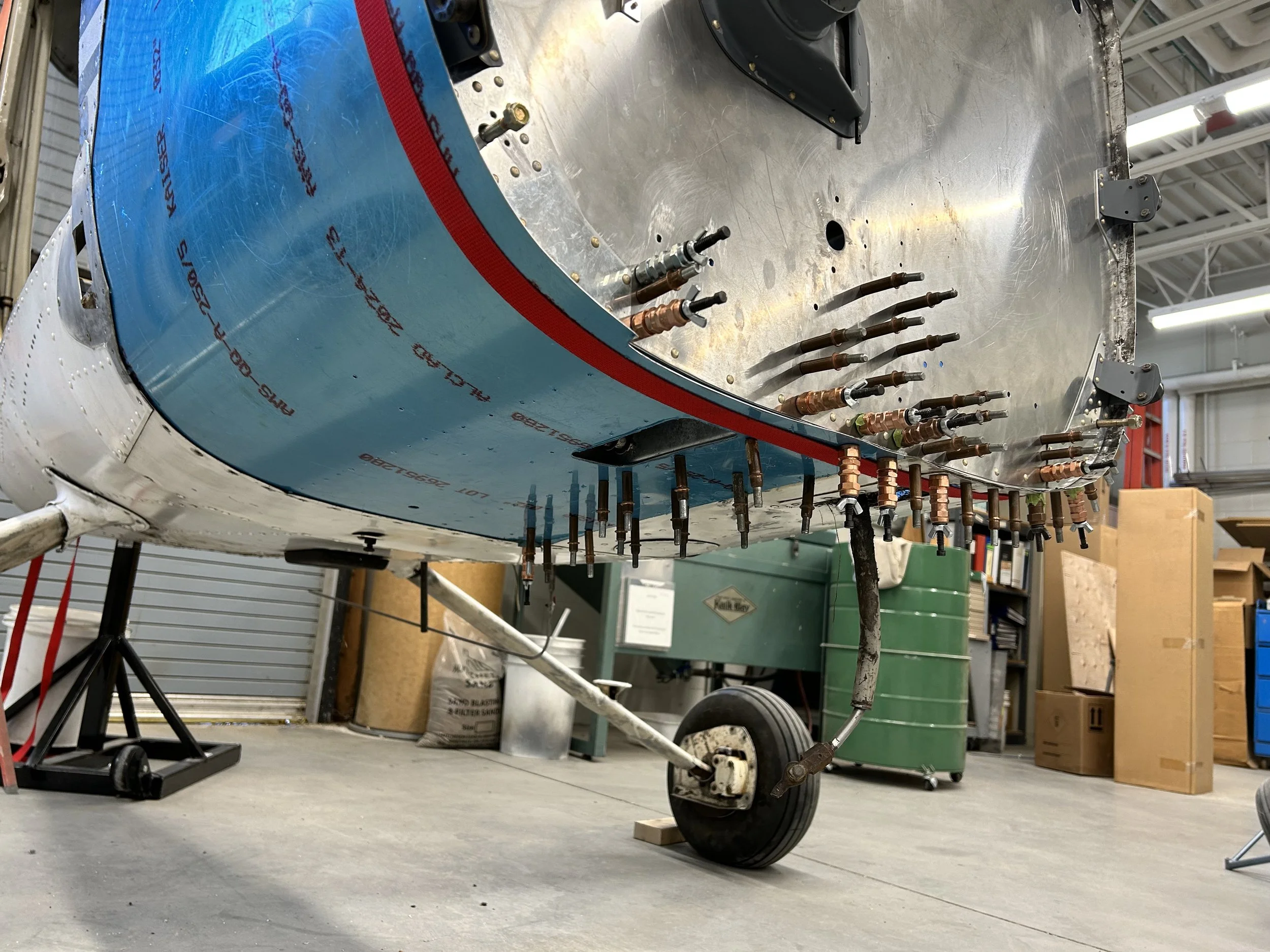
Cleco fasteners holding the firewall and lower quarter panel in place.
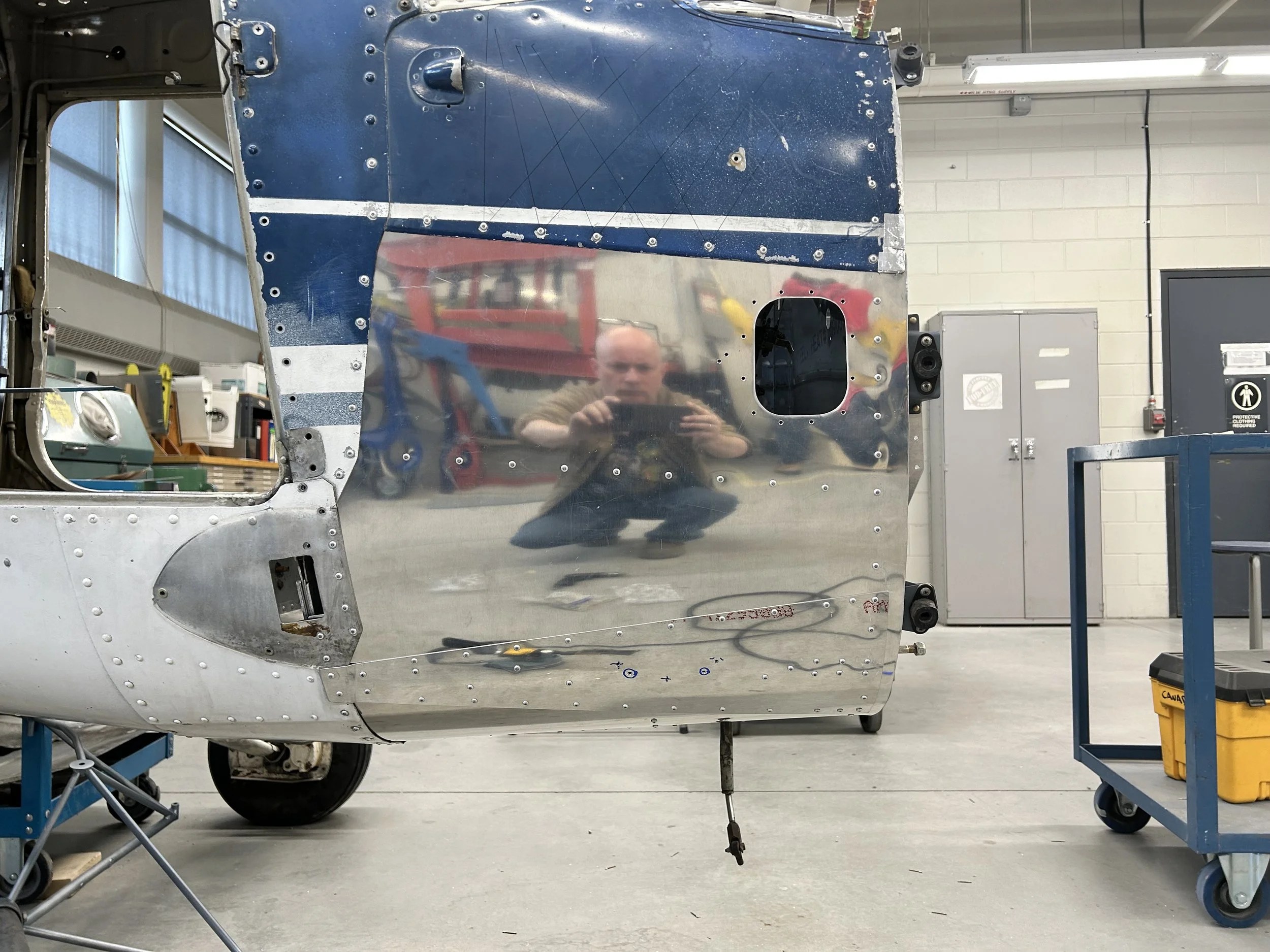
With just about a month left of classes for the term it was time to button things up. The firewall and quarter panel skin have now been riveted into place. All rivets for this process were CherryMax or HuckMax blind rivets. These are not the rivets you would find in the Cessna 150 SRM, but were chosen for two reasons. 1) we had several bags of each laying around the shop and felt that they could be put to good use on a project that no longer needed to meet its Type Certificate, and 2) they allowed me to continue with the project solo and not have to wait until someone else had the time to hold the bucking bar. Moving forward with these rivets ensured that I could complete the project on schedule. Sure, they are not the correct type, but they are considered a 1-1 replacement for standard rivets with engineering approval, and it’s not like this aircraft is ever going to fly again anyway. At some point I had to make due with what I had.
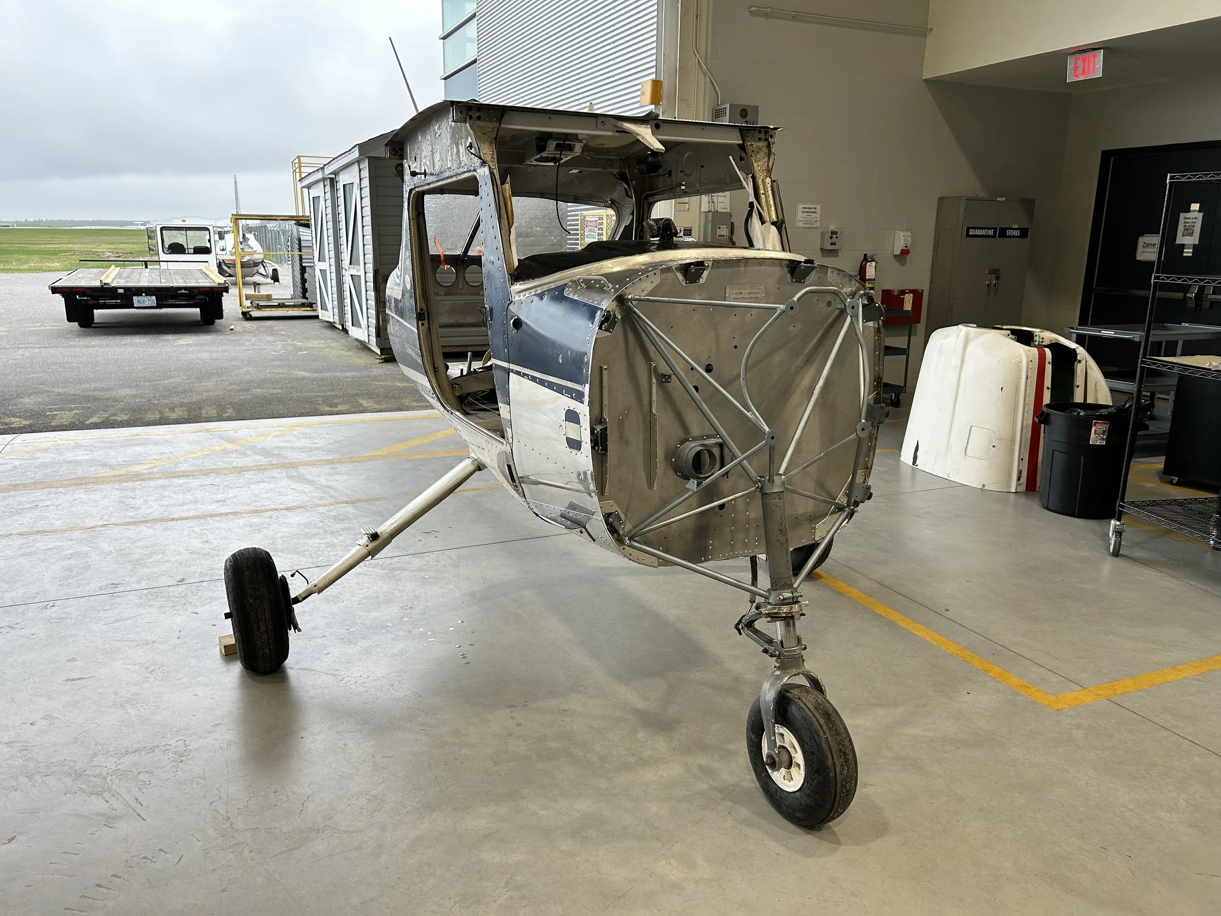
The project was officially completed on May 10th, 2023 with the installation of the front landing gear and engine mount.
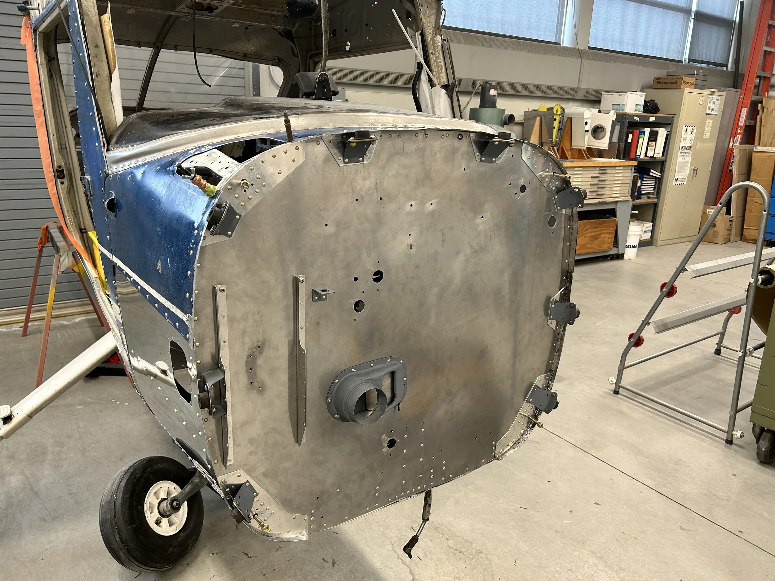
All fasteners in place except for around the area still to be patched.
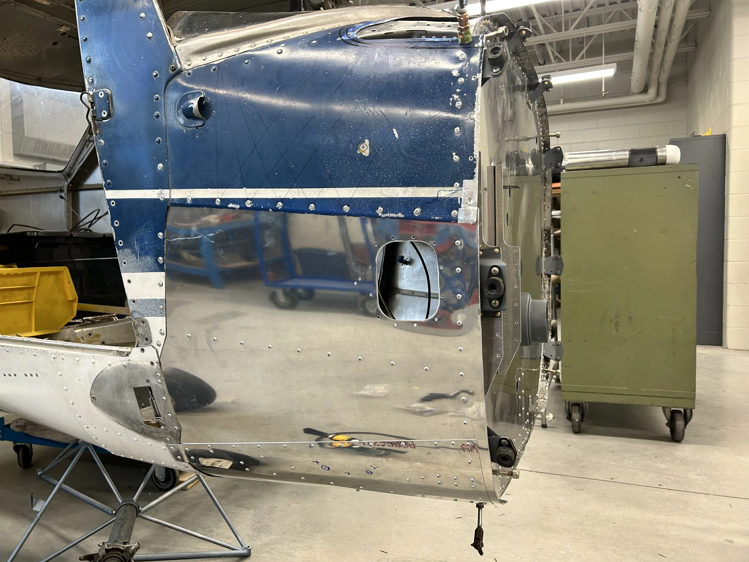
The cabin air vent is inside, but not yet installed.
"Everything's shiny Capt'n..." - Kaylee Frye

With the front wheel and engine mount installed - Project complete.

Project Complete.
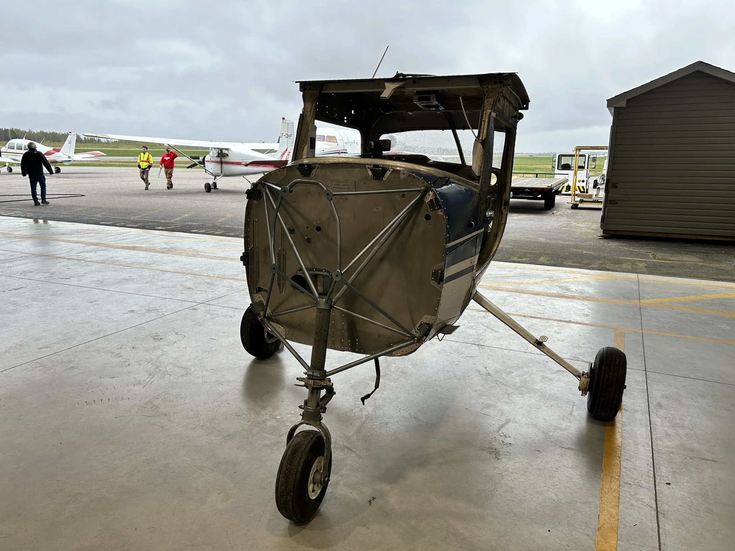
Back home in the hangar.
Back home in the hangar.