Another very enjoyable project at the school is the creation, from drawings, of a metal and composite ‘wing’ structure. We call it a wing, but the reality is it more closely resembles a very small flap or aileron as the final assembly has no airfoil shape to it at all. I would have liked to have made mine with an actual airfoil, but we had to follow the drawings and I suppose this makes it easier for people to finish.
The main assembly consisted of 3 identical wing ribs with lightening holes, 3 leading edge D Nose sections, and 3 attachment brackets. Along with those, an 18” wing spar, leading edge skin, upper and lower main skins, and an interior support for a clear plastic lens. All structural material is 2024-T3 aluminum of various thicknesses from 0.020” to 0.040”. Tools used to create the parts included shears, a box and pan brake, hole punch, punch and dies, as well as various hand tools.
Along with the all aluminum main structure, a composite ‘wingtip’ is also created. The process includes using a set of down-scaled drawings to create a full sized station plan, turn those stations into a foam plug, build a mold, and create a fiberglass wingtip from that mold using all the processes and techniques you would find in the real world. The process is very much the same as the process I’ve used in the past to make fiberglass hulls for RC boats starting with just drawings. So I was able to hit the ground running on that portion of the project.
Click on the images below for more details.
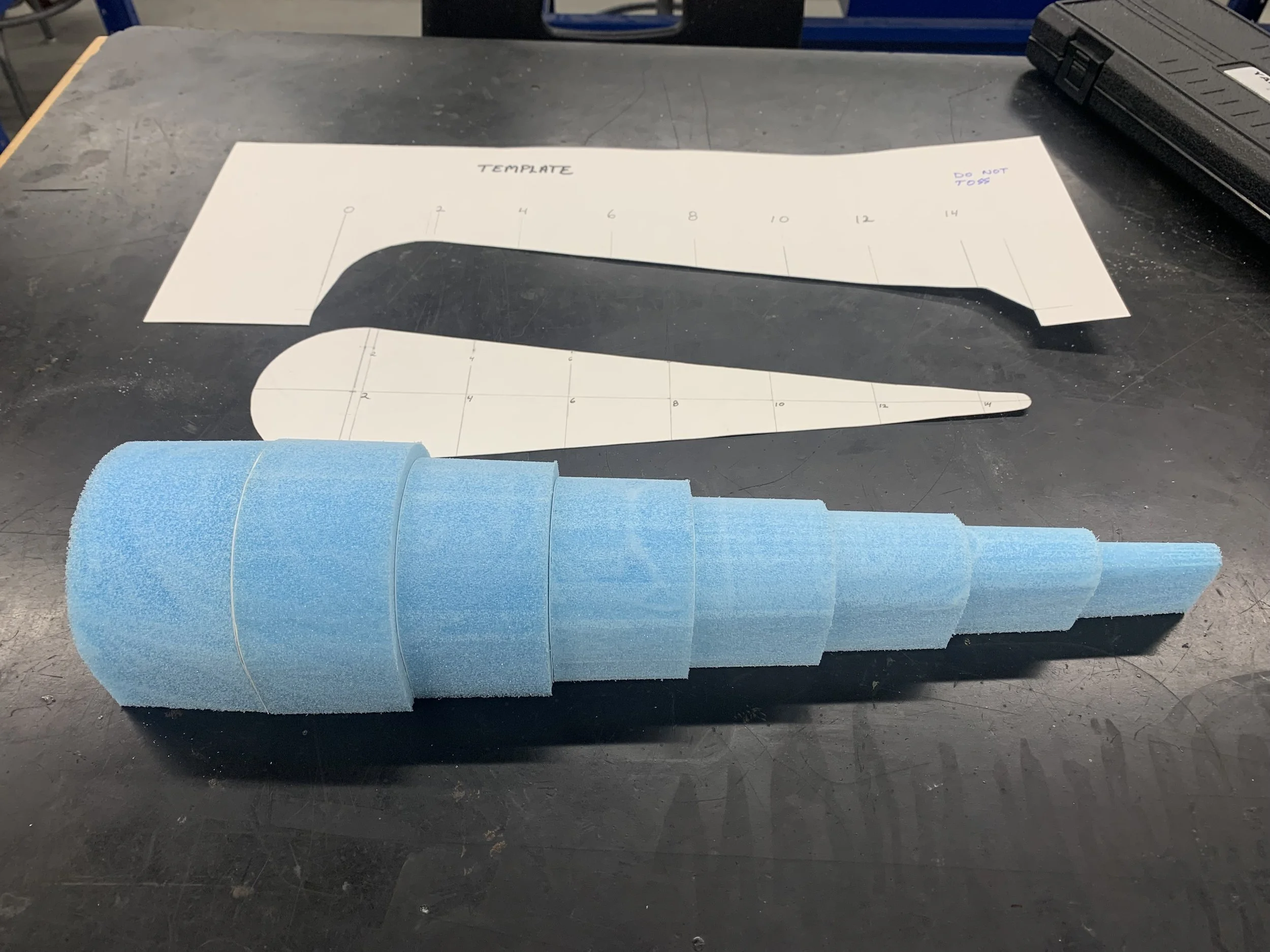
The foam plug of the wingtip made from stations. This blocked out form is sanded to its final shape.
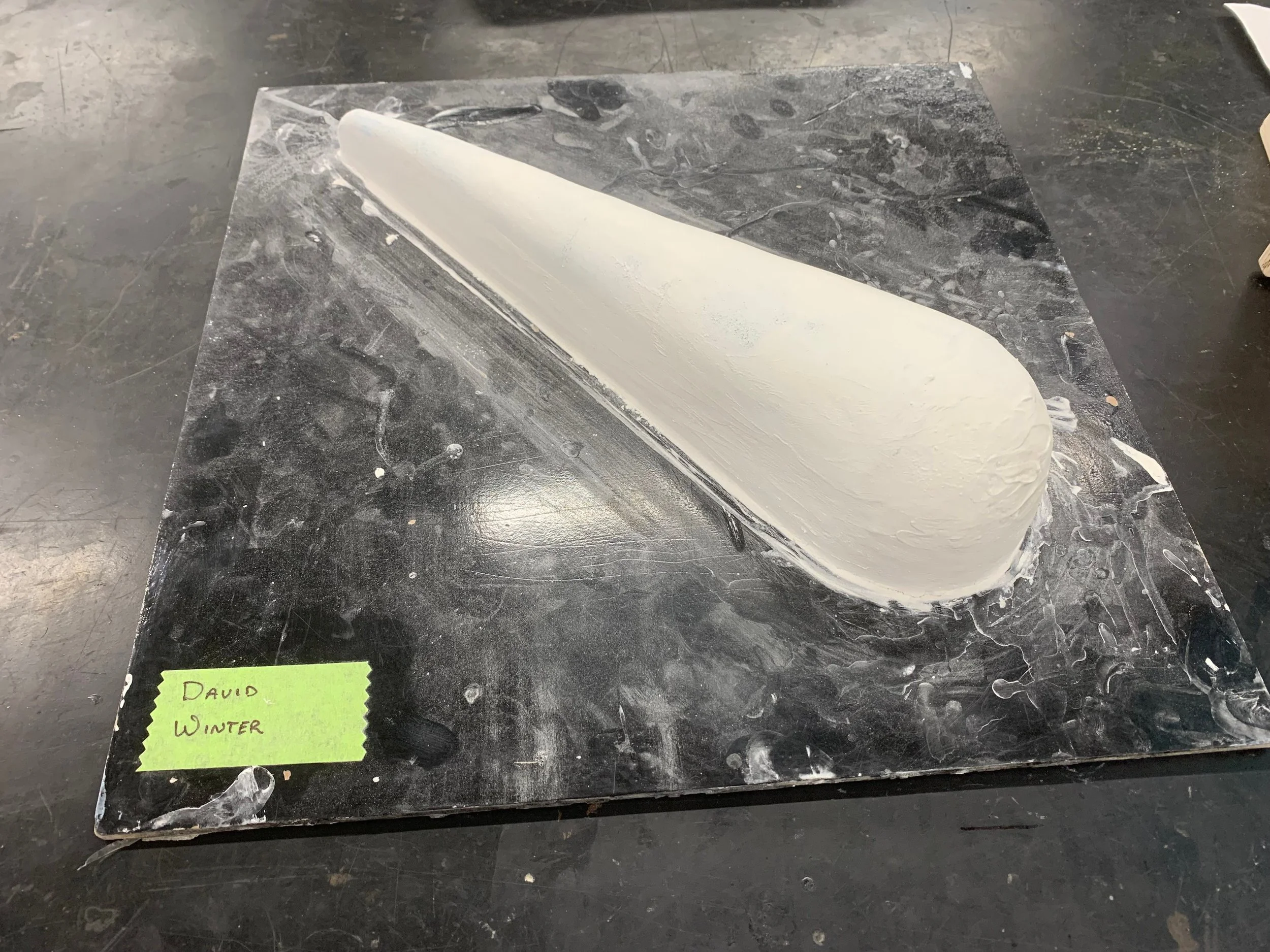
The plug is sealed, ready for mold creation.
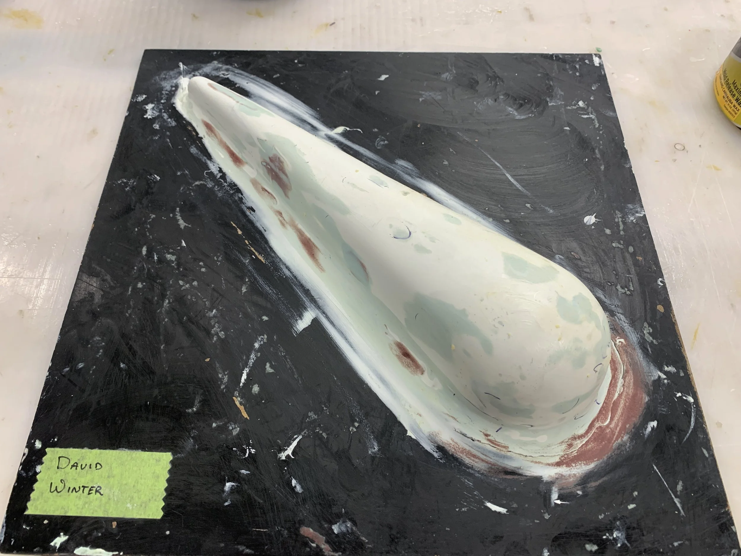
More Bondo than resin, the wing tip plug is shown here with its first coat of mold release wax coating.
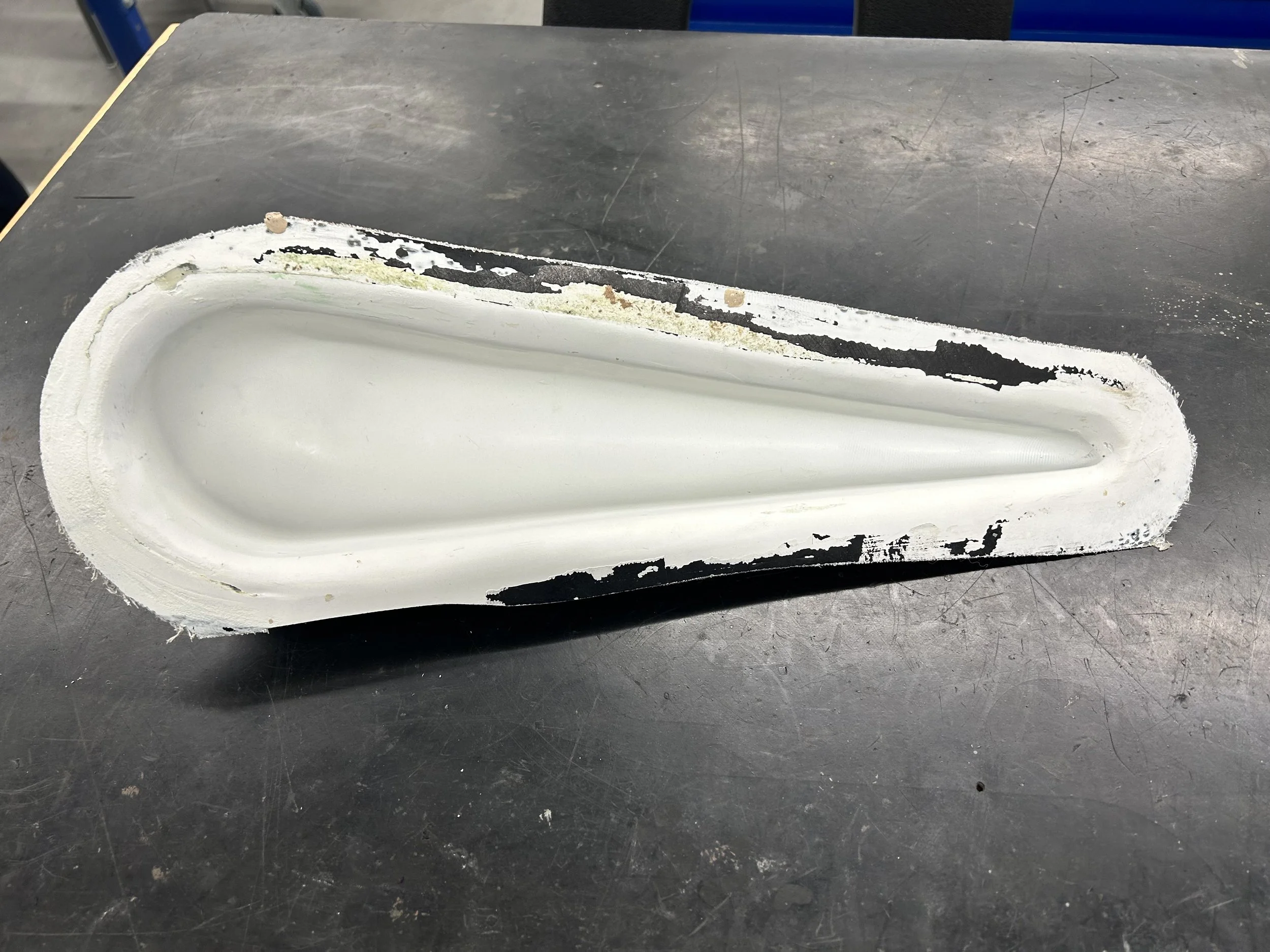
The final mold pulled from the plug, ready to be used to generate the final part for the wingtip.

Smooth-On silicone rubber was applied to the mold to be used as a vacuum bag. The tube is the vacuum inlet.

After a few hours to cure, the silicone is removed from the mold. Perfect.
The below images cover the construction of the primary metal ‘wing’. All parts were fabricated from sheet stock of various thicknesses ranging from 0.025” to 0.063”. The D nose sections were manufactured by pressing material on a mold into rubber. The remainder parts were made on a brake. Assembly with various rivets.
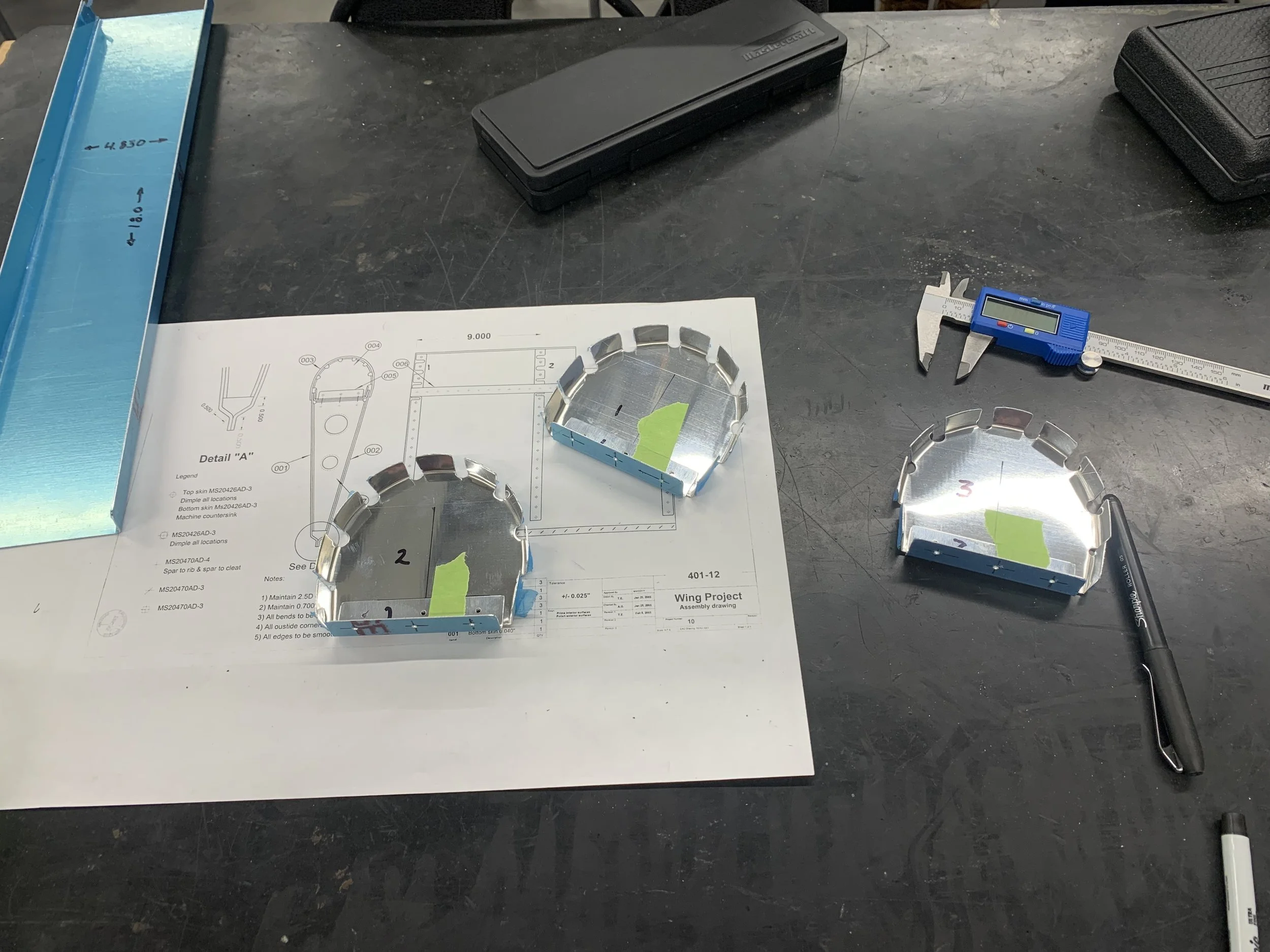
All parts fabricated from scratch, including the 'D Nose' parts, their spar attachment brackets, wing ribs, skins, etc...

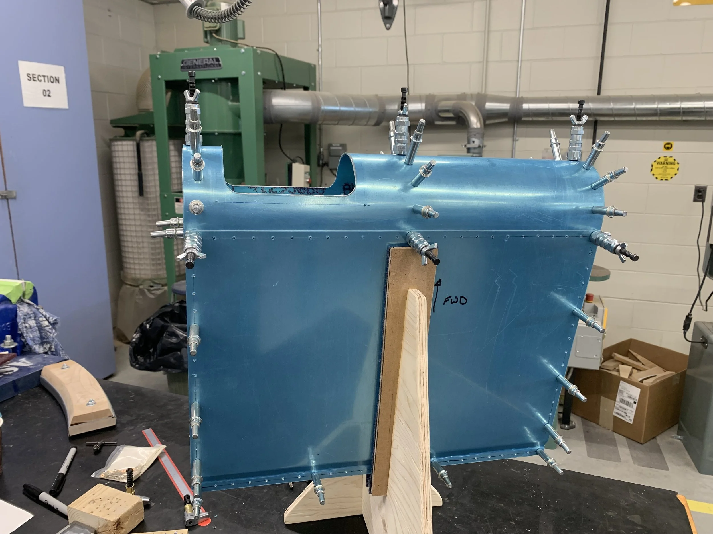
The rear of the wing cleco'd.
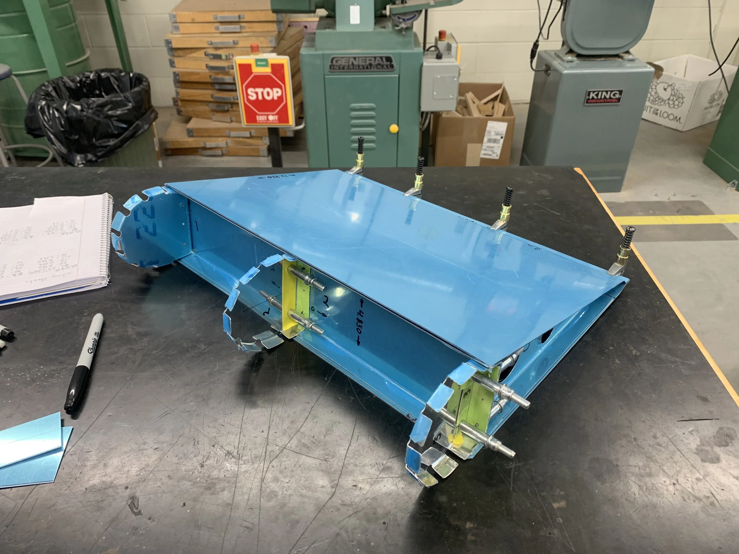
The rear of the wing cleco'd.
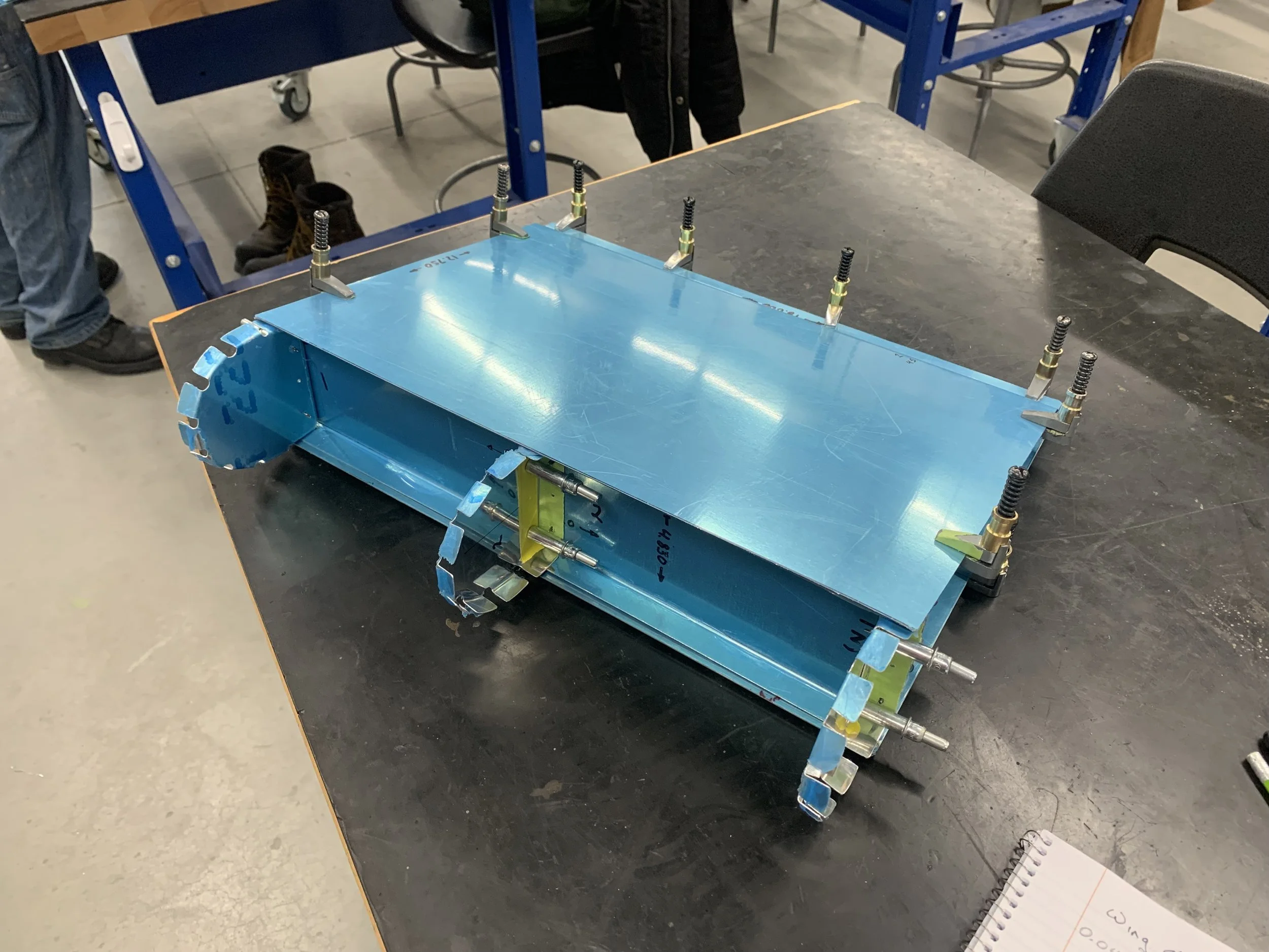
The rear of the wing cleco'd.

The wooden 'holding fixture' for the wing.
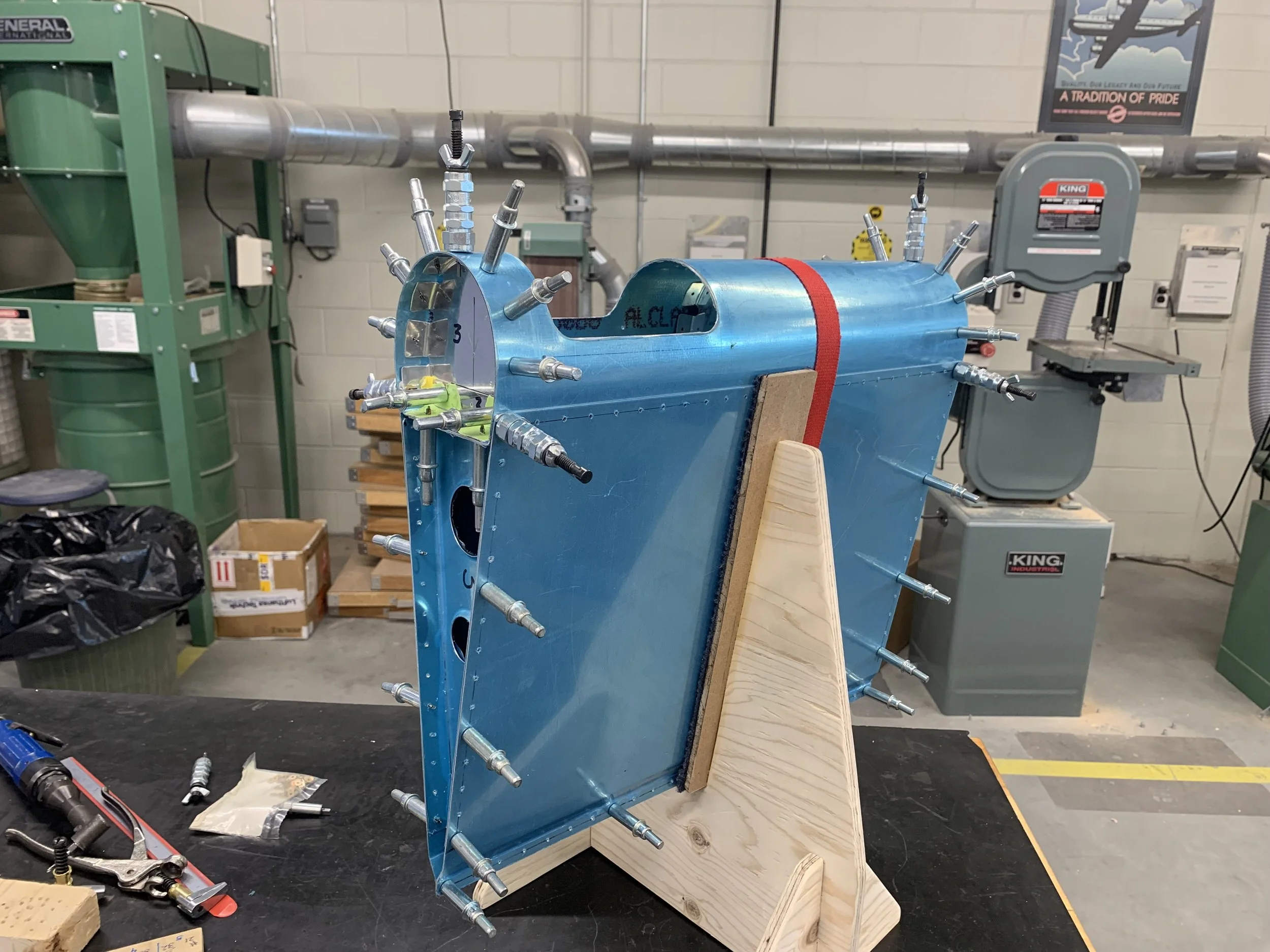
Wing with leading edge and temp fasteners.
Wing with leading edge and temp fasteners.

Internal structures of rib, d section, and bracket removed and given a prep of Alodine.

All internal structure has now been primed and ready for final assembly.

The first rivets installed.
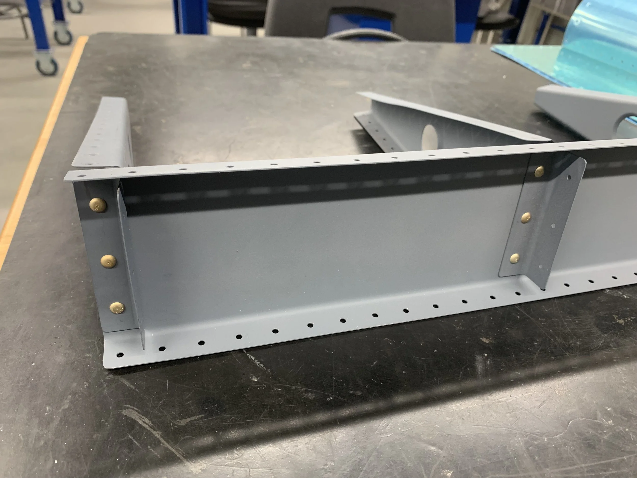
Final assembly of spar, brackets and two of the three ribs.
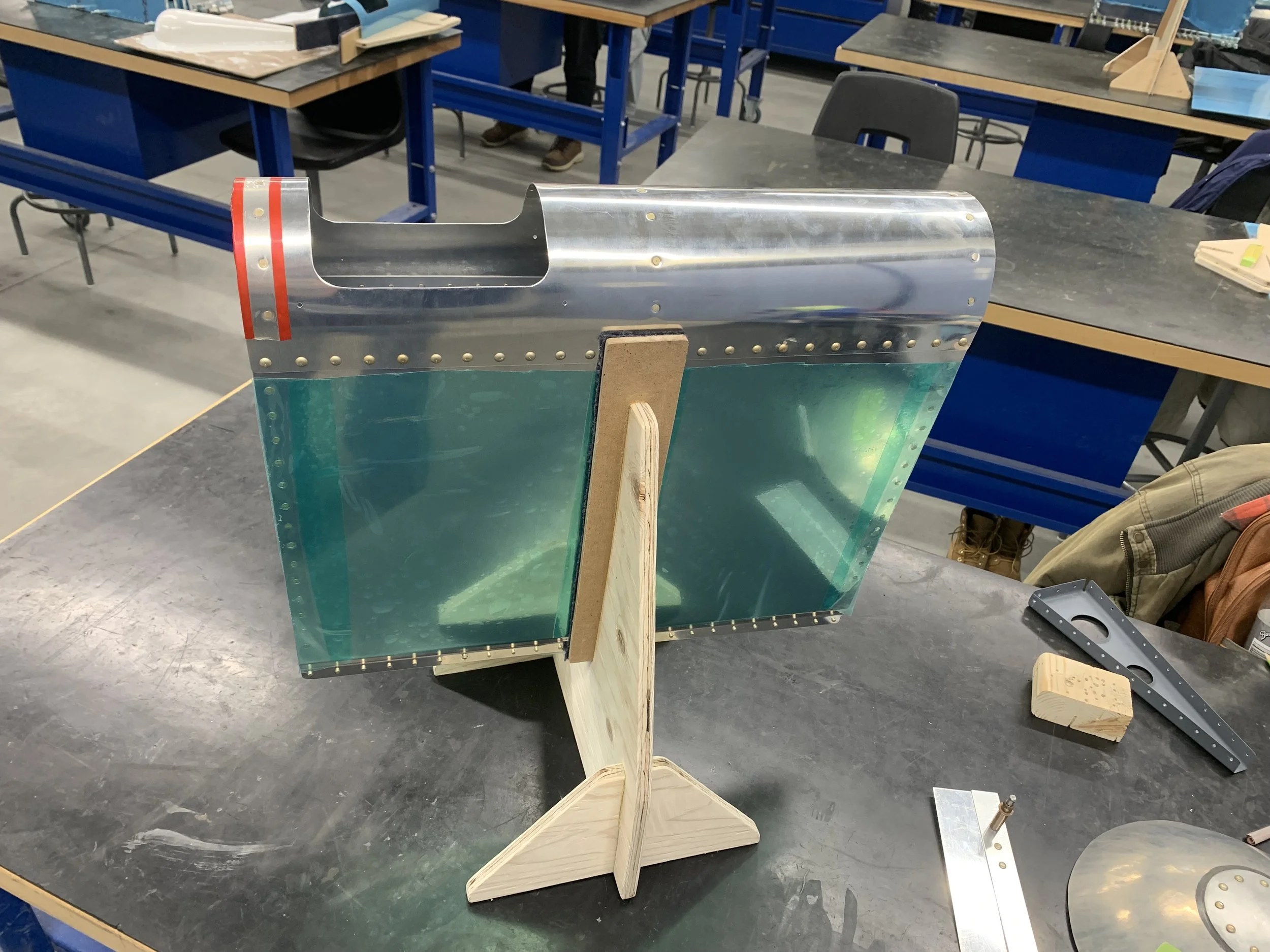
And that's it. The whole wing assembled and riveted together. Next step is installing the clear perspex lens.
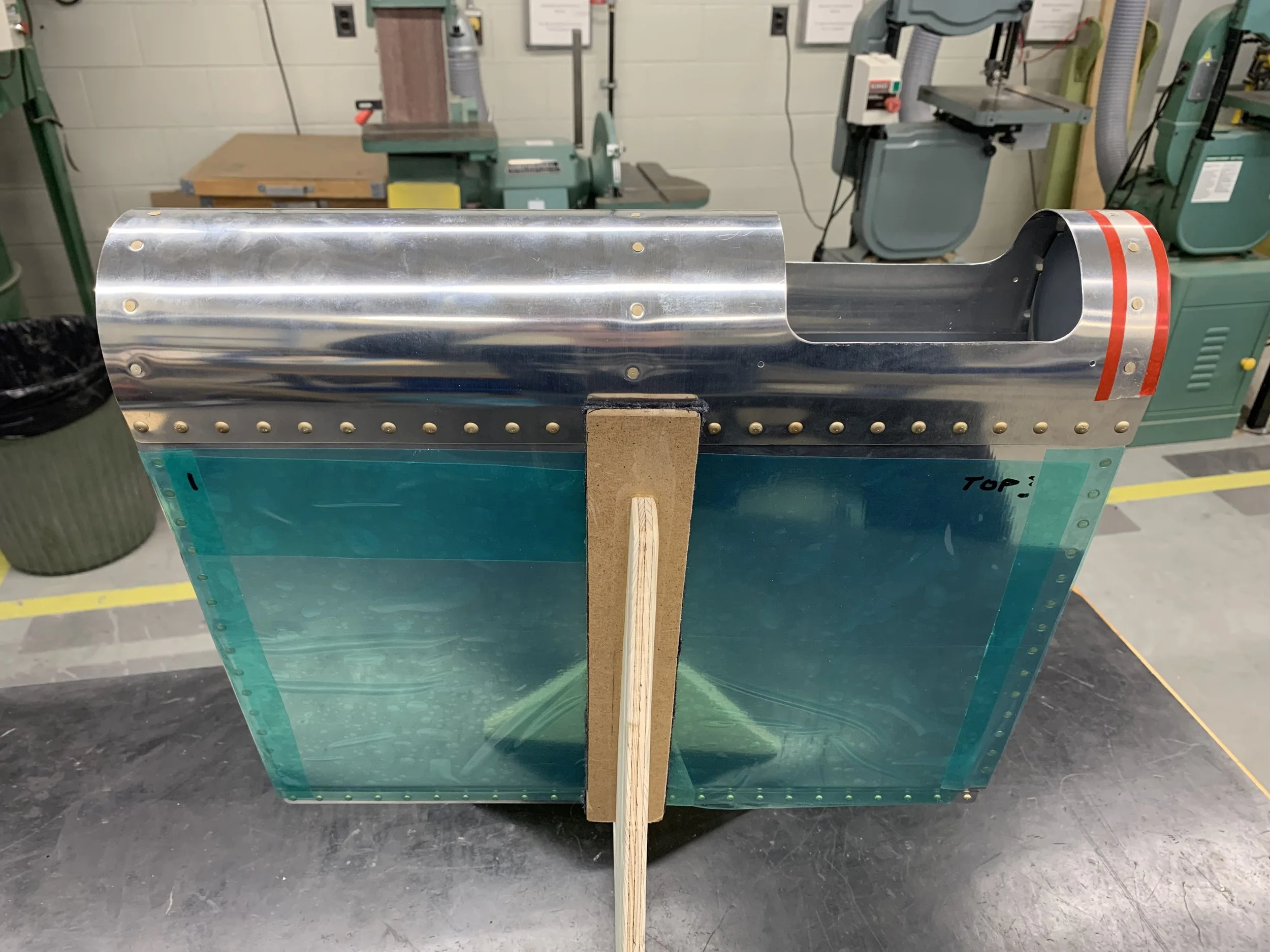
And that's it. The whole wing assembled and riveted together. Next step is installing the clear perspex lens.
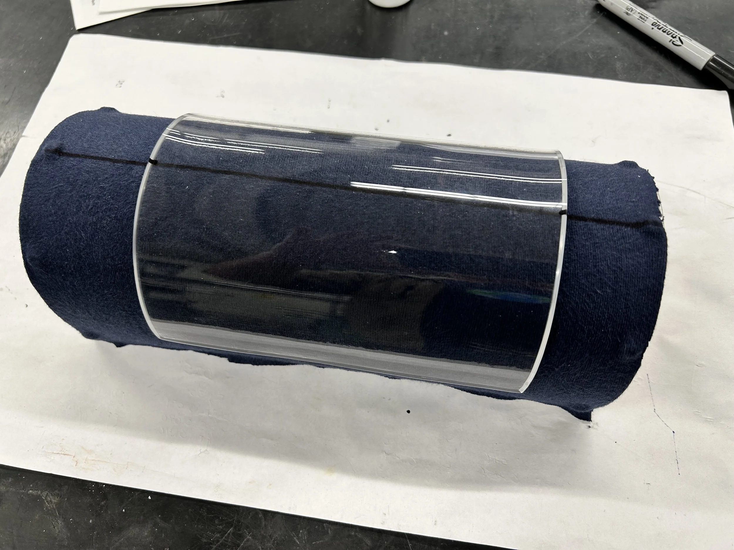
With the wing structure finished, it was time to move on to creating the acrylic lens. This was done by forming acrylic sheet over a custom form.

The formed lens with internal retainer test fitted.